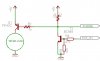
I have a circuit, here is a snip of it..
the incoming BUS_ON signal is 5volts when on...
the SS_PIN is outgoing to SlaveSelect on SPI port of AVR
so i take the inverted bus_on and send it through a 1k to the base of a PNP trans, emitter to 5v and collector to source of device
anyway... what i need to happen and it does in this circuit is power up a device that needs about 500ma when bus_on is high... like i said it all works fine here..
it all works, until i find out i need to control a 12v device same 500ma
if i connect the emitter to 12 volts, it no longer works, the transistor is always on
why?
and better yet how do i fix?
i now need to drive a 12 volt device that uses about 500ma...
could a P-channel mosfet work here?
attached is the partial schematic
some help please...
maybe some education too")
mitch
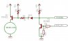
the incoming BUS_ON signal is 5volts when on...
the SS_PIN is outgoing to SlaveSelect on SPI port of AVR
so i take the inverted bus_on and send it through a 1k to the base of a PNP trans, emitter to 5v and collector to source of device
anyway... what i need to happen and it does in this circuit is power up a device that needs about 500ma when bus_on is high... like i said it all works fine here..
it all works, until i find out i need to control a 12v device same 500ma
if i connect the emitter to 12 volts, it no longer works, the transistor is always on
why?
and better yet how do i fix?
i now need to drive a 12 volt device that uses about 500ma...
could a P-channel mosfet work here?
attached is the partial schematic
some help please...
maybe some education too
mitch