Continue to Site

Welcome to our site!

Electro Tech is an online community (with over 170,000 members) who enjoy talking about and building electronic circuits, projects and gadgets. To participate you need to register. Registration is free. Click here to register now.

  • Welcome to our site! Electro Tech is an online community (with over 170,000 members) who enjoy talking about and building electronic circuits, projects and gadgets. To participate you need to register. Registration is free. Click here to register now.

Help to find best small size high IFSM diode

Status
Not open for further replies.

Roger44

Member
Hello

The 1N5400 series diodes have 200A IFSM's for a diam of ony 5,3mm. Is there a better diode to resist a short circuit when size is a premium. I'll have to give you more info.

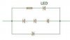
The attached image is of a small circuit to fix inside a wall-mounted on/off switch, with the LED protruding through a hole in the face plate. When current flows the LED lights so I know when I've left a small several hundred watt blower on in the attic.

I tested with 1N4007's but when I made a short-circuit (Murphy's Law) they obviously expired before the 2A electromagnetic bipolar circuit breaker tripped.

Rather surprisingly it worked with 1N4007's running a 1.5kW vacuum cleaner even without a resistor to protect the LED.

Thanks
 

Attachments

  • voyant diode solution 3.JPG
    voyant diode solution 3.JPG
    7.1 KB · Views: 348
If all you want is to detect when your device is on. Then placing your light indicator (LED, neon bulb...) across your power leads rather than in series would be cheaper, easier, use less parts and would be safer. Of course it would be placed between the switched source voltage and your device. Adding a fuse in line with your LED is always a good idea if designing into AC power-rated in mA not Amps. The resistor in series with the LED would need to allow your required LED current to pass as the LED will act as a halfwave rectifier. So many ways to do this!
 
Last edited:
I don't have a neutral power lead present behind the wall switches otherwise yes it would be simple as they are readilly available with small neon bulbs in the shops The resistor is of a few tens of ohms.

I have tested some doiodes from the bottom of my drawers in wire-touching 220V short circuits with a 2A circuit breaker, the non-survivors don't explode, they just go conductive apparently. Is this always the case?
 
Aha, I see what you're trying to do there. Pretty clever, actually: you're using the forward drop of those 3 diodes to generate ~3V for a LED. That should work fine.

But the problem is that I don't think any diode is going to be able to survive the extremely high short-circuit current should there be one. I might be wrong, and others here might be able to point you to a device that would be able to absorb that much energy.

How about making the circuit with a sacrificial component that would blow in case of a short and save the diode? That way the circuit would still work, even if your indicator light doesn't. Haven't thought of how you would do that; still scratching my head.

Question: how much room exactly do you have inside your switchbox? I'm wondering if you could cram in a high-current stud rectifier, covered in shrink-wrap or something.
 
Last edited:
If all you want to know is if current is flowing you may want to consider using one of these little units. They cost about $12 USD including the LED indicator and mount. Voltage is not a factor and any current exceeding 750 mA lights it. Additionally the primary line can be looped through the donut hole so even less current is required. Max current is 20 AAC. CR Magnetics is just an example as devices like this likely have dozens of distributors.

Option two is simply roll your own. Make a coil using maybe 28 or 30 AWG wire on a small bobbin and place a single small diode in series with one leg and the LED.

This method has you totally non intrusive and isolated from your AC mains. Current flow, diode on, no current, diode off.

<EDIT> DigiKey carries them for a little over $10 USD they can be seen here from DigiKey. </EDIT>

Ron
 
Last edited:
Kewl. Just the thing I was thinking about getting to monitor my electric water heater to try to optimize its use.

The hopeless DIYer in me has to ask: is this the sort of thing one could make? I'm guessing it's what? a ferrite core with a couple thousand turns of fine magnet wire around it, and a rectifier (or maybe not, just the LED).

It's pretty amazing to me that even a line-voltage wire (120 here in the U.S.) run through this can generate enough voltage/current to light a LED. Apparently, electromagnetism works!
 
Hey Guys, your good. I posted this thread a couple of weeks ago on a french Futura science forum and got no help whatsoever.

Second286, your mentioning a fuse in series with the LED got me to thinking. Here I am looking for a diode that survives short duration mains short-circuits, what about the LED that will have more that a hundred volts across it with just a few tens of ohms resistor to protect it.
In the forward direction to my knowlege LEDs have, unlike diodes, very limited surge current capapability and after a few half cycles of conduction the junction will overheat.
In the reverse direction their breakdown voltage is practically nothing, so would the juction go in the very first inverse half cycle?

Would any fusing system be able to protect a LED plus small series resistor against hundreds of volts. If the answer is no, I'm kind of wasting my time looking for super diodes, just take 1 or 2A diodes, any old LED, and find a way to protect the whole circuit.
Or forget about protection, and if someone makes a chort circuit - maybe never -just replace the circuit. Six components soldered on a small piece of veroboard costs nothing and takes just a few minutes. Here I've got a nagging worry. I's at my son's house + gandchildren. Any chance that when it blows it could cause a fire. It's inside a small plastic orange or yellow box behind the wall plate, sharing room with a good few 1.5mm wires as it's a double switch.

Carbonzit, concerning room, I could put additional things in a 6x6x2 inch junction box hidden behind a bookcase. All the wires converge on this box so I can add in parallel or in series.
I'll study the link now. Thanks everybody
 
Last edited:
Kewl. Just the thing I was thinking about getting to monitor my electric water heater to try to optimize its use.

The hopeless DIYer in me has to ask: is this the sort of thing one could make? I'm guessing it's what? a ferrite core with a couple thousand turns of fine magnet wire around it, and a rectifier (or maybe not, just the LED).

It's pretty amazing to me that even a line-voltage wire (120 here in the U.S.) run through this can generate enough voltage/current to light a LED. Apparently, electromagnetism works!

Hi Carbonzit

My guess as I have not opened one of the small ones up is they would be a miniature version of the attached images. Just a small (tiny) current transformer. The first image is a 200:5 current transformer that uses an iron core (just an iron ring) with turns of magnet wire wrapped around it. The second attached image shows it opened up. This one uses two parallel conductors of magnet wire. The mains voltage matters not as it is purely a current device. One of the mains current carrying conductors is simply passed through the center hole. The main advantage is total mains isolation.

I would guess that one could easily be made using a ferrite core or iron core with minor effort.

Another trick along these lines that could likely be used would be to hack a simple GFCI (Ground Fault Circuit Interrupt) circuit breaker as they use a pair of coils working as current transformers. A Google of how they work should yield some images of their innards and workings in detail.

Ron
 

Attachments

  • Coil 1.jpg
    Coil 1.jpg
    154.7 KB · Views: 398
  • Coil 3.jpg
    Coil 3.jpg
    258.1 KB · Views: 330
Second286, your mentioning a fuse in series with the LED got me to thinking. Here I am looking for a diode that survives short duration mains short-circuits, what about the LED that will have more that a hundred volts across it with just a few tens of ohms resistor to protect it.
In the forward direction to my knowlege LEDs have, unlike diodes, very limited surge current capapability and after a few half cycles of conduction the junction will overheat.

In the reverse direction their breakdown voltage is practically nothing, so would the juction go in the very first inverse half cycle?

Roger44:

From your second post-you have no neutral to work with. Though I would like to respond to your quote above:

The resistor (R) would not be 10s of ohms, but rather: (Vavg-Vdiode)/Idiode. Where Idiode is about 20 mA. Assuming 120 Vac-then (R) would be greater than 5,000 ohms.

A second resistor could be placed in parallel with the LED to reduce the high reverse voltage, down to 2 Vac, or lower. Basically you would be placing an LED across a voltage divider. Or capacitors could be used instead of resistors for the voltage divider. The caps would form a voltage divider due to there impedance.

Since you have only one line to work with-the solution "Reloadron" poses would handle the job more safely. Tap off a small current via a Toroid to power your circuit.
 
Last edited:
second286, the diode + LED solution can be inserted in series behind the mural switch, the 3 diodes produce a 1.8 voltage drop for the LED connected in parallel, the small resistor is the usual series LED protection resistor, which for 1.8V can be left out. My first idea was in fact to insert in series a simplea resistor that would would produce a 1.8V drop for the LED, but for this you need to know the load's current consumption to calculate the R. The 1N4007 diode solution works with 60W bulbs and surprisingly a 1.5kW Philips vacuum cleaner. The diodes were quite warm!

A voltage divider requires a voltage drop which is rarely available behind a wall switch, unless the switch is off, in which case you can put a small neon which glows when the switch is off. A simple solution to locate outside light switches in the dark.

Idid try a 630mA fuse in series with a 1N4007 diode and it worked. It blew so fast that there was hardly any short circuit spark. However, as I mentioned I didn't test it with a LED. I've got a feeling the LED will go first. I"ll check this when I'm back home in two weeks.

But the magnetic solution is in all ways far more attractive. My ol' ferrite fod aerials plus primary transformer wire, I can't wait to get home.

By the way, a French company Legrand sells a wall switch without neutral (Celiane 47007) for 40 euros that lights when the current is on. A magnetic solution? If nobody has an answer i"ll open one when I get back and have a look inside.
 
Last edited:
But the magnetic solution is in all ways far more attractive. My ol' ferrite fod aerials plus primary transformer wire, I can't wait to get home

Prob'ly better to use a doughnut-shaped core through which you pass the "primary" conductor, dontcha think? But just for laughs you could probably wrap a couple turns of your 220V wire around a ferrite rod for a "proof of concept" test.
 
If nobody protests within 24h, can I suggest opening a new thread for the electromagnetic solution?

You can always open a thread for whatever trips your trigger. Actually it would be more of a CT (Current Transformer) type solution than magnetic solution. :)

Ron
 
I'm on holiday, can't get a FreeWifi link, the hard drive is failing, so I'm squatting someone's portable. Maybe it's simpler to continue with the present thread.

I was thinking of drilling a hole through a two cm long piece of ferrite rod to pass the current carrying wire through, and then winding a beehive type coil along the ferrite (so that most of the coil wire would be parallel to the current carrying wire). Never tried drilling through ferrite and I'm not even sure this is the best theoretical geometry.

Then I would close this coil wire on itself and wind a few turns of more wire as a current transformer for the LED. I suppose this secondary coil would be wound in the same plane as the primary coil.

The result would be something long and narrow, whitch seems to contrast with the coil solution on sale above.
 
Status
Not open for further replies.

New Articles From Microcontroller Tips

Back
Top