Continue to Site

Welcome to our site!

Electro Tech is an online community (with over 170,000 members) who enjoy talking about and building electronic circuits, projects and gadgets. To participate you need to register. Registration is free. Click here to register now.

  • Welcome to our site! Electro Tech is an online community (with over 170,000 members) who enjoy talking about and building electronic circuits, projects and gadgets. To participate you need to register. Registration is free. Click here to register now.

Help (Score Board)

Status
Not open for further replies.

linkthewise

New Member
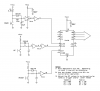
Hi, I need some help making a score board with TTL, I'm using two 74192 and two 7474 and two anode 7 segmet display. But I'm having some troubles doing the manual up/ down pulse. For now I'm using two NE 555 in one shot configuration, but it doesn't work. Could some one give me one example, because when I use the astable mode theres a lot of bounce.
 
But I'm having some troubles doing the manual up/ down pulse. For now I'm using two NE 555 in one shot configuration, but it doesn't work.

Are you building a scoreboard with manual inputs? That is, someone pushes an up/down button to advance/reduce the score? If so, all you likely need to do is debounce your pushbuttons. You could use an RS latch for each pushbutton, built from, say, a quad NAND gate (a 7400 or equiv). Then each pulse feeds the up/down inputs (separately, of course). You may also want a debounced pushbutton on the CLR input to clear the display.

As there are many ways to debounce a switch, you'll have to pick one that suites you. I would recommend checking out the following:

http://www.ganssle.com/debouncing.pdf
 
So with the latch RS, I wont need a timer for the pulses?. Coz I've try debouncing with a 7414 a Schmitt trigger and it didn't worked.
 
So with the latch RS, I wont need a timer for the pulses?

That's right. A debounced pushbutton being pushed by someone provides the pulses to the respective up/down inputs, if that's what you want. But you have yet to state what you want. It's hard to help without you being more forthcoming.

Also, why don't you please post your schematic.
 
You mean like this

I found this schematic, do you think this will work?
74192-up-down.gif
 
Last edited:
I found this schematic, do you think this will work?

We're getting closer, good.

But dude, that's way too small for me to see what's really happening. In principle some of the scheme looks fine, but the devil's in the details, which no person could possibly parse at this magnification. Please post the source URL for your diagram.

In your little drawing, it looks like an astable oscillator is providing pulses to the counter via two pushbuttons, up and down. That's a bad way to go for several reasons, 1) the switches will bounce causing your count to be all over the place, and 2) depending on when the user hits the switch the clock edge could be at a bad place, again causing a weird count. Plus I can't tell what the two NAND gates between the clock and pushbuttons are supposed to be doing; it looks like gibberish...

What's your clock rate? It looks like maybe 2Hz, which means it's not really useful (it's slow). In your implementation the user must hold the button down until the correct count is reached, which could get old at that rate. Why not have the user punch the button the requisite number of times to get to the proper score? That's easier to implement, too. Drop the clock, and debounce two pushbuttons, each driving the up/down pins. You ought to add a reset button too, to clear the score.

A clock with somewhat higher rate might be useful in getting the score to some intermediately high value, say 50, without tiring the user by pushing buttons, too.

Think these things through. Then you can make it happen...
 
Last edited:
You're right

with the clock at 2 Hz the response of the count is not as I expected. So I'll try to do it without clocks, just debouncing just as you said.

Well I try but I can't do it. The count is not right yet could any one post a schematic for the debounce, I try using a 7414 debounce and a latch RS, without any success. The problem appear when I'm trying to connect the down in the count to the latch, because the up stops working and the down count, counts in a strange way. But when I disconnect the up count, the down count works fine. It works when I place one of the pins to Vcc, but when both (Down and Up) are connected, something happens and one stops working and the other counts wrong.
 
Last edited:
I try using a 7414 debounce and a latch RS, without any success. The problem appears when I'm trying to connect the down in the count to the latch, because the up stops working and the down count, counts in a strange way. But when i disconnect the up count, the down count works fine.

You need one debounced momentary pushbutton connected to the UP input. And you need a second debounced momentary pushbutton connected to the DN input. Then you push one OR the other. Have you tried that? Because I'm confused at to what you're saying above.

The count inputs must see a rising edge. The RC debouncing circuit on page 12 of the aforementioned doc should work just fine. (And then, once you find that the debounce period is too long , i.e. your patience is being taxed before you can push the button again, say every 100-200ms, you may have to change things again :) )
 
Last edited:
Try this, it should get you started:
 

Attachments

  • debounce.PNG
    debounce.PNG
    32.3 KB · Views: 379
Last edited:
Try this, it should get you started:

hi Corey,:)

Dosn't the 'unused' clock input on a LS192 have to be High while the 'other' clock is pulsed Low, in order for it to register the low going pulse.?
 

Attachments

  • esp02 Nov. 01.gif
    esp02 Nov. 01.gif
    20 KB · Views: 258
Last edited:
Dosn't the 'unused' clock input on a LS192 have to be High while the 'other' clock is pulsed Low, in order for it to register the low going pulse.?

Hey Eric,

Good catch. Yes, after taking a second look, the unused input must be held high. He'll need a second inverter on each of the counting inputs.

EDIT: Eric also kindly pointed out that the original R values were good for a CMOS Schmitt Trigger, but wouldn't let the input get to a valid low for the TTL part. Try the new RC values as posted in the updated drawing above. If you're using R2, it's calculated for proper timing AND typical Vt- (900mV), but may need to be bumped down yet further to accomodate worst case Vt- (600mV), say to 1.1k (600mV/560uA=1.1k)
 

Attachments

  • 74192.PNG
    74192.PNG
    8.4 KB · Views: 252
Last edited:
I've try doing the debounce with your schematic

It doesn't worked. As I said before it works when there only one push buttom conected, but when I try to conect both the problem appears again. It counts by two, i mean it goes like 0, 2 , 4.
 
Last edited:
It doesn't worked. As I said before it works when there only one push buttom conected, but when I try to conect both the problem appears again.

That drawing was updated recently to alter the RC values, it also added a second inverter to each up/down input. Your circuit is wired that way, i.e. according to the updated drawing? Double check it...
 
Status
Not open for further replies.

Latest threads

Back
Top