Hi, it's been a long while since I did any electronics - I still have bread boards and I think I've got a PIC programmer somewhere but I've forgotten just about everything I knew!
I want to modify a part of a car circuit and could do with some help working out how to do it, hopefully it's quite simple.
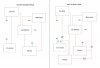
On the car in question there is a device which only runs with the ignition on, I want to keep this but also have a switch to operate it manually. I have identified that the device itself has a feed from the Alternator which provides 12v+ when the car is running, when 12v is detected on this pin it will allow the device to run (runs from a seperate 12v feed)
So for part one I just need to be able to apply 12v to this pin, do I need to put any protection in place so that I'm not sending 12v up the wire to the alternator? and making other things think the engine is running? I still want to keep the original system in place this will just be an override switch.
Secondly the said device also requires a small 12v motor to be running elsewhere on the car. So again I could do with applying 12v to a pin on the motor but again it will receive 12v at other times so I don't want to damage anything.
Then finally to confuse things even more, once this is tested and if it works well, then I want to add a second battery to run the device from, the device can use a bit of power and I don't want to drain the battery. The fuse rating is 25amp but to be honest most power would be used in the first 2 minutes. I want to add a second smaller battery and fit a split charge relay to allow the car to charge the second battery. I would probably change the main feed to the device over to this battery so it always uses the second battery, the 12v feed to trick it to think the alternator is running wouldn't matter as the draw on that would be tiny, but the small 12v motor could do with running from the aux battery during the time I want to force the device to be on.
So I would have two different 12v feeds to the one 12v motor, there is a possibility they could both be on at once.
Hopefully that makes sense and any advice would be appreciated, if I haven't made anything clear please just say what you need I could try and knock up a diagram if that would help?
I want to modify a part of a car circuit and could do with some help working out how to do it, hopefully it's quite simple.
On the car in question there is a device which only runs with the ignition on, I want to keep this but also have a switch to operate it manually. I have identified that the device itself has a feed from the Alternator which provides 12v+ when the car is running, when 12v is detected on this pin it will allow the device to run (runs from a seperate 12v feed)
So for part one I just need to be able to apply 12v to this pin, do I need to put any protection in place so that I'm not sending 12v up the wire to the alternator? and making other things think the engine is running? I still want to keep the original system in place this will just be an override switch.
Secondly the said device also requires a small 12v motor to be running elsewhere on the car. So again I could do with applying 12v to a pin on the motor but again it will receive 12v at other times so I don't want to damage anything.
Then finally to confuse things even more, once this is tested and if it works well, then I want to add a second battery to run the device from, the device can use a bit of power and I don't want to drain the battery. The fuse rating is 25amp but to be honest most power would be used in the first 2 minutes. I want to add a second smaller battery and fit a split charge relay to allow the car to charge the second battery. I would probably change the main feed to the device over to this battery so it always uses the second battery, the 12v feed to trick it to think the alternator is running wouldn't matter as the draw on that would be tiny, but the small 12v motor could do with running from the aux battery during the time I want to force the device to be on.
So I would have two different 12v feeds to the one 12v motor, there is a possibility they could both be on at once.
Hopefully that makes sense and any advice would be appreciated, if I haven't made anything clear please just say what you need I could try and knock up a diagram if that would help?