Continue to Site

Welcome to our site!

Electro Tech is an online community (with over 170,000 members) who enjoy talking about and building electronic circuits, projects and gadgets. To participate you need to register. Registration is free. Click here to register now.

  • Welcome to our site! Electro Tech is an online community (with over 170,000 members) who enjoy talking about and building electronic circuits, projects and gadgets. To participate you need to register. Registration is free. Click here to register now.

Help required.. Limiting max voltage output of 0-5v dc MAP sensor

Status
Not open for further replies.

rolanddrums

New Member
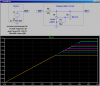
Hi guys, I need help either making or buying a simple voltage limiter that will limit the voltage output of a conventional automotive 0-5v dc output pressure sensor to cira 3.7 volts. The sensor has 3 wires ...0v 5v supply and 0-5 v output to the ecu which varies dependant on manifold pressure. I want the max output capped at 3.7volt ( this normally occurs at 15 psi manifold pressure) , so even if the pressure increases further output will still remain at 3.7 volt.
NB the voltage v pressure 'graph' must not change at anything below this point. Some user adjustment of the voltage cap value would be handy ( say 3 to 4volt )
For many of you guys this will be laughably simple.
ps I know what a resistor and diode are, I understand parallel and series and I can solder ...but thats about it
...Many thanks in advance...Roland
 
This **broken link removed** MAY or MAY NOT work. It's definately more complex than you need. All I know is it's designed to intercept a sensor signal and modify it.
 
Here is a circuit using my favorite part, the TL/LM431. The pot selects the limiting level. In the simulation, the pot wiper is moved from 10% to 90%. The X axis is the MAP sensor voltage, the Y axis is the signal sent to the ECU.
 

Attachments

  • DF140.png
    DF140.png
    35.9 KB · Views: 840
Last edited:
Wow, thanks for the prompt and informative replies guys. I think I will have a go at the circuit you show. What does 'U2 ' and 'U3' mean?, And I guess TL/LM 431 is the transistor part number . ( Im getting eveything from Maplins ..Im in UK btw).
The diagram of the MAP sensor you show refers to some numbers but I guess I can ignore all that ?.I have the MAP sensor already as is part of the car.

One final thing I found another solution surfing the web, that being to use a (say) 3.6 volt 0.5 watt Zenor diode bridged across the signal and 0v wires. Although this gives no adjustability , is it regarded as a good way of doing it? I dont want to fry anything or get a slightly non flat line after 3.6 volts.
Thanks again.
 
U# where # is a number usually refers to Integrated Circuits in schematics. I've also seen IC1, IC2 etc.
U2, would be better shown as R# or RV1; RV usually means Resistor, Variable
Q# is used for transistors and D# is used for diodes, but I've also seen TR# for transistors
V# is use for tubes or Valves
S# is used for switches, F# for fuses, and L# for inductors and C# for capacitors
The #'s just increment and sometimes some are left out. You might see in a schematic that say U3 was the last designation used.

Designations for resistors get wierd too: R1=10,000 or R1=10K or R1=10R3 all mean 10,000 ohms.

The solution was "simulated", so the sensor must be too.

You did ask for adjustibility.
 
Last edited:
Wow, thanks for the prompt and informative replies guys. I think I will have a go at the circuit you show. What does 'U2 ' and 'U3' mean?, And I guess TL/LM 431 is the transistor part number . ( Im getting eveything from Maplins ..Im in UK btw).
The diagram of the MAP sensor you show refers to some numbers but I guess I can ignore all that ?.I have the MAP sensor already as is part of the car.

One final thing I found another solution surfing the web, that being to use a (say) 3.6 volt 0.5 watt Zenor diode bridged across the signal and 0v wires. Although this gives no adjustability , is it regarded as a good way of doing it? I dont want to fry anything or get a slightly non flat line after 3.6 volts.
Thanks again.

The TL431, also known as an LM431, is an adjustable zener diode, in effect. The 470 Ω resistor suggested is there to avoid damage to the sensor or too much current to the TL431, and it may not be needed because the sensor is unlikely to be upset by being shorted out, and the short-circuit current may well be very small anyhow. It's good practice to include it as it is easier to do that than it is to investigate the sensor characteristics in enough depth.

What this all means is that the 3.6 V zener is an almost identical idea to the circuit shown with the TL431.

You will always get a slightly non-flat line. It is just a matter of how much change you can stand. The advantage of the TL431 is that you could wind it down to 3.55 V, so if it rises to 3.6 V at the maximum input, then it won't matter.
 
Last edited:
Hi, ok thanks again. I have just tried using a solitary 0.5 watt 3.3 volt Zenor, and I am getting the 'voltage creep' you refer to at higher sensor output voltages.
ie At 3.75 volts output from the MAP sensor the Zenor holds the voltage at 3.4 v (acceptable) . But at at 4 volts sensor output the Zenor only keeps it down to 3.85v ( not so good) .
Would either connecting 2 x Zenors in parellel or series help in keeping the voltage creep at bay, or is the only solution going down to say a 3v Zenor?....What I want idealy is a flat line after 3.4 volt to the ecu... whether the sensor is throwing 3.5v at the zenor or a mor challanging 4.5v .
Best Regards Roland GTT
 
Unlike a normal Zener, the LM431 has an internal opamp using error feedback to control it's set output voltage, so it has a "flat line" output...

Ignore the "reference designators"; like U2, U3, R1, R2. They are there simply as place holders in the schematic diagram.
 
Last edited:
Ok, so idealy I need the full monty circuit , but if I want to use 1 (or 2 max) components , is there any way of getting a flatter output. The guy at Maplins says using ONLY a Zenor is wrong.. He says I should also be using a resistor in series on the signal feed, between sensor and Zenor....Is this right? Wouldnt this pull down the voltage ECU receives even below 3.3 volt ( 3.3 v Zenor used), ?
 
Without knowing much about the innards of the Map sensor, I would use the series 470Ω resistor to prevent its output from being subjected to excessive current.

I'm guessing that the input impedance of the ECU A/D converter is quite high, so the series 470Ω resistor will not degrade the accuracy while the MAP sensor's output is to the left of the knee in the output curve.

The LM431 has huge advantages over a conventional Zener; the limiting is absolutely flat, it is more stable over temperature, and it is adjustable with a pot. Why would you even think of using a Zener?, especially when the TL431 costs ~$1
 
Last edited:
Ok......I think I will try it. The LM317 in the diagram you kindly supplied has 3 connections...Sorry to sound thick, but will I know which wire goes to which on it when i get it? Also Maplin dont stock it ( they tried both part numbers you gave). Is there another 'equivalent' available?
Thanks.... Roland
 
Try Farnell

They also provide a link where you down load the data sheet, which shows the pin out.
 
Last edited:
Hi, Ok, Ive found some pics of LM431 ....Pin 1 it calls 'ref' , Pin 2 'anode' , & pin 3 'cathode'.
Looking at the symbols is the following correct?.... bit confused as I always thought anode was + and cathode was -.
Pin 1 (ref) goes to the wiper of the 50K pot.
Pin 2 (Anode) goes to Earth 0v
Pin 3 ( Cathode) taps into the 0-5v signal.


Yes, the bar is the cathode (K) and goes to the ECU input downstream from the resistor. The anode (A) goes to ground. In a Zener, or active Zener, like the LM431, the conventional current flow is backwards through the arrow. It is afterall, the "reverse breakdown" that is being exploited
 
Last edited:
Hi Mike, Ok Im realy confused now. Your diagram shows ( after the series resistor) the 'crowbar' side on the diode going to the + signal , and the 'triangle' side of the diode connected to 0 v ( negative).
Also I looked up LM431 on 'Mouser', and theres nearly 50 different LM431's , all with different prefix and suffix. sorry to be a pain..
..Ah ok youve edited your post ...I thought I was going crazy.
 
Last edited:
Select "Shunt regulator"

Basically prefixes refer to the manufacturer so an NE555 is made by Signetics, LM555 National and TL555 Texas Instruments.

Suffixes usually refer to package type, but they could refer to accuracy, temperature specs, ROHS complient.

Briefly, from the pics, I saw two different lead configurations (inline and triangular) and surface mount. Leaded packages are getting hard to come by now, but are easier to prototype with. 60/40 solder has largely been replaced because of ROHS (The EU directive:Reduction of Hazardous Substances). The replacement solder has a higher temperature and reliability issues with respect to developing whiskers that short to nearby pads.

On the Mouser website there is a datasheet link. Take advantage of it. It should explain the variations. The package with leads would likely be the best for you.

As an example, there is a Military, industrial and Consumer temperature range.
 
Last edited:
Ok I have ordered the LM431 in TO92 style from Mouser. Many thanks to all of you for your help, and Mike for the circuit diagram including component values . I will let you know how I get on . ..regards Roland.
 
hello after almost 10 years :)))

I need exactly the same solution. Did that circuit worked? do you have some infos?

Thx
gusti
 
Status
Not open for further replies.

Latest threads

New Articles From Microcontroller Tips

Back
Top