Continue to Site

Welcome to our site!

Electro Tech is an online community (with over 170,000 members) who enjoy talking about and building electronic circuits, projects and gadgets. To participate you need to register. Registration is free. Click here to register now.

  • Welcome to our site! Electro Tech is an online community (with over 170,000 members) who enjoy talking about and building electronic circuits, projects and gadgets. To participate you need to register. Registration is free. Click here to register now.

Help! Reading Voltage with Arduino

Status
Not open for further replies.

Ali Ghazemian

New Member
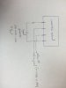
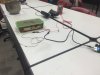
Hi guys! I'm trying to build a device to measure the electrical resistivity of a paste (cementitious materials) using Arduino Uno. Four steel probes are put inside the paste (jumper wires attached to them). Two outer probes apply AC signals (Square wave signals- Frequency 1 kHz- Voltage(peak to peak)= 14 V) and two inner probes should measure the potential difference. Then the resistivity could be calculated by a formula. Please take a look at pictures: https://www.dropbox.com/sh/a3ijaxgpmv45xf3/AAB2-HQxs8aqYsi3nWg8W8b4a?dl=0

I managed to apply the desired AC signals, but the issue is about reading the potential difference (two inner probes) by Arduino. When I use a multimeter (set to AC mode) I read some values (voltage) which should be correct, but using Arduino as the same time I read different values! I cannot see why! I connect of the two inner probes to Arduino ground pin and the other one to analogue pin (A0) to read values, then I convert it to voltage ( float voltage = sensorValue * (5.0 / 1023.0); ) and print it to serial monitor. I programmed Arduino to read values 10 times during a second and report the maximum value only. There is not even a relationship between values (Examples: (Multimeter: 0.712 V, Arduino: 1.15 V)-(Multimeter: 0.68V, Arduino: 1.10V)-(Multimeter: 0.67V, Arduino: 1.03V)). Can anyone tell me what modification I should do to read correct voltages with Arduino? I would really appreciate any help from you guys!
IMG_2121.JPG
IMG_2119.JPG
 

Attachments

  • IMG_2117.JPG
    IMG_2117.JPG
    1.4 MB · Views: 427
Welcome to ETO, Ali Ghazemian!

We need some additional information.

Please provide for us an exact schematic of your entire setup and the sketch you wrote for the Arduino. Also, include all voltage sources and any external DVMs also attached, in any fashion.
 
Welcome to ETO, Ali Ghazemian!

We need some additional information.

Please provide for us an exact schematic of your entire setup and the sketch you wrote for the Arduino. Also, include all voltage sources and any external DVMs also attached, in any fashion.

Hi Cowboybob and djsfantasi,
Thanks :) To clarify what is happening I got an oscilloscope and repeated the test this time with sin waves (instead of square wave)... I modified the arduino code to sample 2500 times during a second and report the maximum value... Now Oscope, MM, and Arduino give me three different numbers: Oscope(Vp-p): 2.5V, Multimeter: 0.7V, Arduino: 1.55V
The circuit is simple and I have attached the scheme. I will be grateful if you can comment on this and how these values are related. Thanks.

Arduino Code:

/*
ReadAnalogVoltage
Reads an analog input on pin 0, converts it to voltage, and prints the result to the serial monitor.
Attach the center pin of a potentiometer to pin A0, and the outside pins to +5V and ground.

*/

// the setup routine runs once when you press reset:
void setup() {
// initialize serial communication at 9600 bits per second:
Serial.begin(9600);
}


void loop() {
// read the input on analog pin 0:
int sensorValue = analogRead(A0);
// Convert the analog reading (which goes from 0 - 1023) to a voltage (0 - 5V):
float voltage = sensorValue * (5.0 / 1023.0);
// print out the value you read:
float max_volt = voltage;
for (int i=0; i<2500;i++)
{
sensorValue = analogRead(A0);
voltage = sensorValue * (5.0 / 1023.0);
if (voltage > max_volt)
{
max_volt = voltage;
}
delayMicroseconds(5);
}
Serial.print(max_volt);
Serial.println(" V");

delay(1000);
}
 

Attachments

  • IMG_2893.JPG
    IMG_2893.JPG
    555.3 KB · Views: 449
Last edited:
You are attempting to read an AC voltage with an A to D converter that can only read positive voltages from 0 to + 5 volts (Assuming the A to D reference voltage is set to 5 volts.) Also you are reading the instantanious voltage so even if you rectified the AC waveform you would still read some random value between zero and the peak voltage of the waveform. you need to rectify the signal and smooth it. (Or time the sampling to be a some particular point on the waveform.)

Les.
Thanks Les Jones. I will try it with rectifier. Still one thing that does not make sense is that even multimeter which is supposed to report true rms, measures a value which is not X0.707 of peak value reported by oscope (I assume Vrms = Vpeak x 0.707 for sine waves)
 
If you use a simple rectifier using diodes then the readings will not be accurate due to the forward voltage drop of the diodes. To get accurate readings you will need to use an active rectifier. You will find out how to build one using Google. There must be no connection between the AC supply to the sample and the Arduino. The simplest way to ensure there is no connection between the AC source and the Arduino would be to use a transformer between the signal source and the sample. Using a square wave rather than a sine wave would simplify the smoothing of the readings. I am assuming the use of AC is to reduce electrolytic effects.

Les.
 
The OP appears to be trying to evaluate the conductivity of the material in the container.
Electrical conductivity is best determined by an AC waveform and s/s probes of a standard size which permits calibration vs known standards, such as known salt concentrations in distilled water.
I attach a module of my own design which derives a frequency based on the EC of the material under test. In my app a microcontroller will use this via a counter and return a valid EC in mhos. It is used for hydroponics.
An arduino should have T0Ck input which can do the job.
The files are in EAGLECAD.
 

Attachments

  • ECmeter.zip
    13.5 KB · Views: 330
Status
Not open for further replies.

New Articles From Microcontroller Tips

Back
Top