Continue to Site

Welcome to our site!

Electro Tech is an online community (with over 170,000 members) who enjoy talking about and building electronic circuits, projects and gadgets. To participate you need to register. Registration is free. Click here to register now.

  • Welcome to our site! Electro Tech is an online community (with over 170,000 members) who enjoy talking about and building electronic circuits, projects and gadgets. To participate you need to register. Registration is free. Click here to register now.

help PCB probelm

Status
Not open for further replies.

cannibal

New Member
Hello

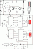
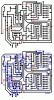
I have circuit which was working perfect in the breadboard
the circuit is attached like it is when was working

when I made PCB and moved all the parts
the buzzer is making non stop sound

I don't know where is the problem

could you please check my pcb to see if I made some connection wrong !!

I checked the soldring and nothing touchs

please help
 

Attachments

  • 1pbb.GIF
    1pbb.GIF
    15.9 KB · Views: 122
  • 2pbb.GIF
    2pbb.GIF
    12.7 KB · Views: 106
If the transistors are BC337 then the pcb for the 555 and transistors is the same as the schematic.

Like I said in the thread about this circuit, the 555 will never time out if one LDR is in the dark. Then the buzzer won't stop.

The pin 2 trigger pin of the 555 must be pulsed through a coupling capacitor then pulled up with a resistor to correct it.
 
audioguru said:
the 555 will never time out if one LDR is in the dark. Then the buzzer won't stop.

yes that feature is needed
(the 555 won't time out if one LDR is in the dark)


if the PCB is correct why you think the buzzer won't stop
like in the breadboard ??!!

do I have to replace the 555 or the transistors ??!!
 
I was double chacking the circuit
and I found that

R4 is brown black yellow
it should be 100K

but in multimeter it shows only 9K

do you think that R4 is the problem that maks buzzer not stoping ?!
 
cannibal said:
R4 is brown black yellow
it should be 100K

but in multimeter it shows only 9K

do you think that R4 is the problem that maks buzzer not stoping ?!
A very bright light (sunlight?) might be needed to overcome the 9k resistor to turn off its transistor.
 
cannibal said:
R4 is brown black yellow
it should be 100K
but in multimeter it shows only 9K
do you think that R4 is the problem that maks buzzer not stoping ?!
You can't accurately measure R4 in circuit. Disconnect at least one end of R4 first before ohm metering it.
 
Status
Not open for further replies.

Latest threads

New Articles From Microcontroller Tips

Back
Top