Electro Tech is an online community (with over 170,000 members) who enjoy talking about and building electronic circuits, projects and gadgets. To participate you need to register. Registration is free. Click here to register now.
Welcome to our site! Electro Tech is an online community (with over 170,000 members) who enjoy talking about and building electronic circuits, projects and gadgets. To participate you need to register. Registration is free. Click here to register now.
paparts, I'm assuming this is a school assignment.
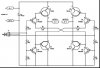
To start with this is called an "H-bridge", commonly used for motor direction control. Look at the possible input (A & B) states. For each input combination, use your transistor theory to see what happens to each of the four input transistors (Q5,6,7,8), and how these control each of the four output transistors (Q1,2,3,4), and thus the states of the outputs (Motor A and Motor B).
If it helps make four copies of the schematic and label the voltages at each point for each of the input combinations.
Is this cascaded? or cascoded? or should I solve it individually? All I know as of now is that they all act as a switch. This darlington transistors have high current gain and thats the problem I am about to findout. Is my idea correct? And also I'll divide it in to 2 since the other side is just the mirror of the other right?
This site uses cookies to help personalise content, tailor your experience and to keep you logged in if you register.
By continuing to use this site, you are consenting to our use of cookies.

")