Continue to Site

Welcome to our site!

Electro Tech is an online community (with over 170,000 members) who enjoy talking about and building electronic circuits, projects and gadgets. To participate you need to register. Registration is free. Click here to register now.

  • Welcome to our site! Electro Tech is an online community (with over 170,000 members) who enjoy talking about and building electronic circuits, projects and gadgets. To participate you need to register. Registration is free. Click here to register now.

Help on creating circuit

Status
Not open for further replies.

heberjm8

New Member
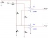
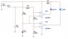
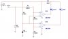
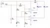
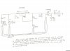
I'm just a newbie circuit designer, which I'm sure is apparent to those of you who see the above circuit and are not. At any rate, I'm trying to create a simple circuit that compares the voltage being delivered from the solar panel to a reference voltage of 15V to the comparator (provided by the 18v battery supply). If the solar panel is NOT delivering a minimum of 15v, the red LED should illuminate. If the solar panel IS delivering above 15v, the yellow LED should illuminate. Rather than making it over complicated by using two seperate comparators (one for each LED), I was trying to simply use an inverter but I don't know if what I'm trying to accomplish is possible with these components. This probably goes without saying, but we obviously intend to use the 18v battery supply to power the LEDs since it is the solar panel we are interested in comparing. The LEDs are your typical 2v ones.


If someone would be kind, please take a look and let me know what things are wrong with my circuit. If you want to be a saint, please provide a circuit diagram of one that might work or resolve whatever issues exist with my current circuit. We are using an LM339 for the comparator and I don't remember the number of the invertor off the top of my head but it is a cmos if I recall. I'll post again with more details regarding the inverter name once I check (the breadboard and circuit is currently at a buddy's house, so I can't check it right this minute). Also worth noting, we use an NTE956 instead of an LM317.

P.S. I have attched the circuit I have designed but it doesn't work and I don't know what is wrong with it. Thanks!


Your help is highly appreciated.
 

Attachments

  • Circuit.jpg
    Circuit.jpg
    369.9 KB · Views: 402
As drawn your circuit has several problems. Given a choice I would use two sections of the LM339 and use something like the attached. I am not nuts about using a pair of 9 volt batteries because of what will be a short life. I would use a 15 volt zener as the reference for the comparators.

Also you may want to give this link a full read. I did not test or simulate the attached but it should give you the idea combined with the link. It was done in haste and we know what they say about haste. :)

Ron
 

Attachments

  • LM339 CKT..gif
    LM339 CKT..gif
    13.6 KB · Views: 625
I know there are several solar panel or battery charge indicator circuits on the web. Have seen several but would have to re search for link.
I recall one was using an op amp as a comparator, has three leds(RED, YELLOW GREEN)
search for battery charge circuits or charge indicator
 
I made a really simple battery indicator using a 4011 to drive a common anode RGB LED for my radio, and it works beautifully. If you make a comparator circuit that can indicates when the battery is charging, and when it's "dead" you can combine it with this circuit. If you want to use it to indicate if the voltage is under, at, or over 15V then you can use the circuit that Ron posted but make it a window comparator.

In Ron's circuit, it will work but you can use an LM393 if you don't want to waste half a comparator. Ron only used an LM339 because Multisim doesn't have an LM393, I had to do the same thing. I ran Ron's circuit and it did work, but I would add a little hysteresis to the comparators. I made a window comparator circuit to work with the display. I have attached the circuits below, and it has an example of 1V above, 1V below, and at 15V. If it is connected to the display, then it will be Red if it is below 15V, Green if it is at 15V, and Blue if it is above 15V.
 

Attachments

  • indicator.JPG
    indicator.JPG
    36.6 KB · Views: 251
  • window.JPG
    window.JPG
    25.2 KB · Views: 456
  • window above.JPG
    window above.JPG
    26.4 KB · Views: 753
  • window at.JPG
    window at.JPG
    26.4 KB · Views: 237
  • window below.JPG
    window below.JPG
    26.4 KB · Views: 259
In Ron's circuit, it will work but you can use an LM393 if you don't want to waste half a comparator. Ron only used an LM339 because Multisim doesn't have an LM393, I had to do the same thing. I ran Ron's circuit and it did work, but I would add a little hysteresis to the comparators. I made a window comparator circuit to work with the display. I have attached the circuits below, and it has an example of 1V above, 1V below, and at 15V. If it is connected to the display, then it will be Red if it is below 15V, Green if it is at 15V, and Blue if it is above 15V.

Actually it was done in Orcad on my home version which does not include P-Spice or any simulation software. It does include the LM393 but I didn't use it because the original poster mentioned having a LM 339 I believe. I thought (operative word being thought) it should work. I also should have tossed hysteresis in there but figured the link on comparators mentioned it (with neat pictures too!). :)

Anymore my snail mail at home and at work is loaded with countless fliers from electronic parts houses and looking at one of them I see these little Battery Monitor kits with a few chips and 7 LEDs for about 7 or 8 bucks (USD). I doubt I could build one for that price. :)

Ron
 
Status
Not open for further replies.

Latest threads

Back
Top