Continue to Site

Welcome to our site!

Electro Tech is an online community (with over 170,000 members) who enjoy talking about and building electronic circuits, projects and gadgets. To participate you need to register. Registration is free. Click here to register now.

  • Welcome to our site! Electro Tech is an online community (with over 170,000 members) who enjoy talking about and building electronic circuits, projects and gadgets. To participate you need to register. Registration is free. Click here to register now.

Help needed with Frequency Counter

Status
Not open for further replies.

malsch

New Member
Hi, I need to design a simple frequency counter to measure the frequency of a square wave input (hence signal conditioning is not needed for now). I have understood the concept that the counter needs to count the input pulses for 1 second and display them on a 7-segment. My problem is how am i going to use the latch function (LE) to keep showing the frequency that was counted.

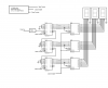
This is what I came up with so far:
**broken link removed**

The input signal (in this case 50Hz) triggers the 1Hz monostable, hence counts for 1 second. The problem is that after that 1 second, the counter resets to zero and recounts to 49 in this case. I need to find a way to keep the counter on 49 rather than going back to zero. Later I will add a 10Hz and 100Hz monostable for decimal points but for now I need to understand this concept.

Thank you.
 
You need a circuit on your counter front end similar to the attached. You need a gate to open the door and allow in the signal to be counted for a specific time interval (1 sec or .1 sec in the example). You need to latch the count so the counter will hold and display it, and finally you need to reset the count to all zeros prior to the next count.

The attached circuit is part of a counter circuit designed by Forrest M. Mims III featured in his Engineers Notebook II circa 1982. Feel free to use newer chips. :)

Ron
 

Attachments

  • Counter Front End.gif
    Counter Front End.gif
    16.8 KB · Views: 195
10q very much :) i will look closer into this design. But doesn't U2C and U2D cancel out each other (because it is like have 2 not gates together)?
 
U2C configured as it is forms an Inverter and U2 C&D together form an AND gate. The 10 K resistors and .001 uF caps form a passive differentiator circuit. That shortens the pulse for the latch and reset functions. See the attached. So the input to U2C is not a nice pulse but looks like the attached. Then we invert the pulse out of U2C using U2D.

Ron
 

Attachments

  • Diff.gif
    Diff.gif
    7 KB · Views: 167
Malsch

Your circuit is a rather uncoventional configuration for a frequency counter.

A free-running monostable is not a good starting point for the timebase, it will not give good accuracy.

Conventionally, a counter will use a crystal controlled oscillator running at a high frequency, typically 1 or 10Mhz. This frequency is divided by a number of counters to produce an accurate 1 second time for the gate.
Note that the gate time does not have to be 1 second, it may be longer (10 seconds) or shorter (maybe a short as 1mS) depending on the frequency to be measured and the required resolution.

JimB
 
Last edited:
Actually to add to the post of JimB the 555 scheme needs to go. Your gate time can't be a function of the frequency to be counted. The gate time must be a function of an independent (and very accurate oscillator as Jim points out). This is where the circuit I posted comes into play. Also using the 74194 there is no need to tie D0, D1, D2 and D3 (pins 15, 1 10 and 9 respectively) to ground.

If you want any accuracy in the least I suggest a version of crystal oscillator as the time base.

Ron
 
I didnt really understand that schematic and how it works. I will look further into the crystal. What i really can't understand is how can I make the counter stop counting after the 1 second pulse (in case of the 1Hz). I tried using state machines so that when the 101 sequence is found, the output stays at logic high and feeds directly to the latch but with the input being the 1Hz, the system didn't work
 
hi,
A problem with the circuit originally posted is that while the frequency is being counted the display is showing an increasing count value, when the 1sec gate period ends, the very next pulse of the input frequency being measured resets the display to 000.
You will only see the last count for about 20mSec, the higher the frequency you are measuring the worse the problem becomes.
The display will be changing so fast you wont be able to read it, and when it reaches it max count it will go back to 000 and restart.!

Ideally you need intermediate latches between the counter IC's and the LED drivers and as Ron and Jim have explained a crystal gate with latch enable at the end of the sample period. OK.?
 
Last edited:
I didnt really understand that schematic and how it works. I will look further into the crystal. What i really can't understand is how can I make the counter stop counting after the 1 second pulse (in case of the 1Hz). I tried using state machines so that when the 101 sequence is found, the output stays at logic high and feeds directly to the latch but with the input being the 1Hz, the system didn't work

hi,
This is a block diagram for a minimal frequency counter,

Included in the crystal block are the components that Ron has shown.

EDIT: drawing corrected
 

Attachments

  • 333.png
    333.png
    190.8 KB · Views: 175
Last edited:
Status
Not open for further replies.

New Articles From Microcontroller Tips

Back
Top