Continue to Site

Welcome to our site!

Electro Tech is an online community (with over 170,000 members) who enjoy talking about and building electronic circuits, projects and gadgets. To participate you need to register. Registration is free. Click here to register now.

  • Welcome to our site! Electro Tech is an online community (with over 170,000 members) who enjoy talking about and building electronic circuits, projects and gadgets. To participate you need to register. Registration is free. Click here to register now.

help needed to understand these circuit symbols

Status
Not open for further replies.
Last edited:
As Eric said they are N.O. push button switches. The small circles in the schematic indicate the points where the switch contact pins are connected to the circuit.
 
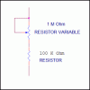
Nice little circuit. Something else to note is on the left there are two resistors. One is a variable resistor. There is a small arrow on it but there is no connection. That is the "wiper" and it would be configured as the attached image.

I may build that after I return from my road trip I start tomorrow. It would have been nice to take along. Oh well.

Ron
 

Attachments

  • Resistors.gif
    Resistors.gif
    4.1 KB · Views: 179
I doubt the circuit will work at all.

An LED supplied by 9V via a current limiting resistor of 470KΩ won't even glow at total darkness.

A transistor with a base resistor of 100KΩ would also not have enough base current to act as a switch.

Boncuk
 
thnx for the answers...
I doubt the circuit will work at all.

An LED supplied by 9V via a current limiting resistor of 470KΩ won't even glow at total darkness.

A transistor with a base resistor of 100KΩ would also not have enough base current to act as a switch.

Boncuk
actually some of the schematics are wrong. and fortunately, many ppl have posted the corrections in comments in the link i gave. those 470k resistors were actually meant to be 470 ohm. and i changed the 100k ones to 10k.

but my circuit isnt yet complete... ill hv to buy the transistor.
will bc1078 be okay as a switching trans.?
 
Last edited:
will bc1078 be okay as a switching trans.?

If you mean BC107 it should work. Any small NPN switching transistoe should work with the correct base resistor. The 2N2222 or 2N3904 being among a few others.

Ron
 
FYI: If you have a Canon digital camera you can do away with the circuit and just script the camera to do time lapse with CHDK.
 
well, nvr mind.... i got a bc548, but couldnt make it work..... the ground-shutter connection always remains closed whenever the circuit is switched on. i tried 100k, 10k, and 47k with transistor base, same result
the red LED blinks with the time interval and the green LED glows continuously.

cannot figure out anything....

the current at base of transistor does vary, but only by about 5 uA. (maybe wrong since my multimeter has a low refresh rate). all i know is that ground-shutter contacts remain closed forever
 
made it.... i had to manage without the transistor. i simply connected the shutter wire to pin 3 and camera ground to -ve terminal of battery. im using a 3 volt source n the cam also runs on 3v, so i dont think that would damage the cam.... or would it?
 
Hi arnab321,

I simulated the circuit just out of curiousity. The green LED is on for a very long time while the red one is only on for the time it takes for an eye twinkle.

The purpose of the circuit isn't quite clear to me.

Would you please explain what the circuit is supposed to do?

Regards

Boncuk
 
this is for taking time interval pics of course. the switching on of the red led is an indicator of the shutter wire being connected with ground wire. (thats what the circuit is supposed to do, but that wont happen without tweaks. thats why i completely got rid of the transistor)

the modifications i made to make it work, apart from the ones mentioned in my prev. posts are:
-replaced the 0.1 uf cap with 220uf cap, for a longer pulse (ine is about... um... say 500ms)
-used a 2m pot instead of 1m for a longer time interval limit.
-runing in 3v supply
 
Status
Not open for further replies.

New Articles From Microcontroller Tips

Back
Top