Continue to Site

Welcome to our site!

Electro Tech is an online community (with over 170,000 members) who enjoy talking about and building electronic circuits, projects and gadgets. To participate you need to register. Registration is free. Click here to register now.

  • Welcome to our site! Electro Tech is an online community (with over 170,000 members) who enjoy talking about and building electronic circuits, projects and gadgets. To participate you need to register. Registration is free. Click here to register now.

Help needed to Set a delay on BC547 / BC557 Circuit

Status
Not open for further replies.

obeids

New Member
Hi Guys!

I am new to this forum. I am a little handy with electronics but don't know the inner workings of components etc.

I have a small little school bell timer which you can set the time to ring the bell. The problem is that the duration that it rings the bell for, is to short. It only rings for around 3 seconds and because we use this electric siren, you hardly get to hear the bell and its off again. So I needed to just keep the relay active for maybe around 8 to 10 seconds.

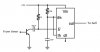
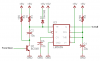
I have opened the unit up and found that it uses a BC547 / BC557 pair to activate the relay unit.

Is there a way for me the keep the relay active for longer by adding a Capacitor or something somewhere in the circuit?
If so, how do I do it? which pins should get the + and which should get the -.

The circuit operates on 5V dc.

Any help would be really appreciated.


Thanks alot
 
Assuming that the bell is turned on by a logic high signal (and I'm not sure that's the case), you could place a 555 circuit like this in line with the signal. I'm not sure if it would work but maybe someone else can chime in and verify or debunk.


**broken link removed**

Basically the old logic signal will trigger another signal with longer duration.

EDIT: I just realized that the circuit above will need a pull up resistor connected to the NPN collector.
 

Attachments

  • bell.jpg
    bell.jpg
    16.4 KB · Views: 393
Last edited:
And of course, the drawing depects a 555 timer. I think the ctl pin sould be tied to ground thru a small capacitor.
 
A diode (1N4148) parallel with the 1KΩ resistor with the cathode connected to +5V won't hurt either.

Boncuk
 
I don't recommend connecting a millifarad (1000uF) directly to the discharge pin (3) of a 555.

Much better values would be 470k instead of 10k for the resistor, and 20uF for the capacitor.
 
I don't recommend connecting a millifarad (1000uF) directly to the discharge pin (3) of a 555.

Much better values would be 470k instead of 10k for the resistor, and 20uF for the capacitor.

That's roughly the same time constant. Just out of curiosity, why is the 1000µF cap a bad idea?
 
1000µF stores a lot of energy, and it might be more than the discharge transistor would like. Since there's no specified limit, it comes down to an educated guess. 1000µF charged to 3.3V would put the equivalent of 3A through the transistor for a millisecond, which would make me uncomfortable.
 
1000µF stores a lot of energy, and it might be more than the discharge transistor would like. Since there's no specified limit, it comes down to an educated guess. 1000µF charged to 3.3V would put the equivalent of 3A through the transistor for a millisecond, which would make me uncomfortable.
That makes sense. Thanks.
 
Thanks to all for your help

Hi Guys

Thanks to all you great guys out there. I am going ti get down to the store and build up the suggested circuit and see what I can get out of it. I'll keep you guys posted with the results
 
Even though the OP appears to be somewhat MIA, here is an updated schematic with the suggested improvements. The increased delay should be about 9.4 sec. Also, I think that depending on the specifics of the timer circuit and provided the original assumption about a logic high signal turning on the bell are correct, a current limiting resistor and a pull down resistor might need to be connected to the base of the NPN.

555_bell_timer-png.44131
 

Attachments

  • 555_bell_timer.PNG
    555_bell_timer.PNG
    18.9 KB · Views: 1,761
Hi Guys

Thanks to all you great guys out there. I am going ti get down to the store and build up the suggested circuit and see what I can get out of it. I'll keep you guys posted with the results

Hey there. Do you know if the assumption about a logic high turning on the bell is correct? If it's not the circuit will need to be modified. Also, Is the signal already current limited from the timer circuit?
 
Hi.
The signal comes in from some Massive IC. It seems to be a digital Logic IC that controls everything on the board. It's a PIC if i'm not mistaken. I'll try to upload a photo tomorrow.
The Unit does have a seting to change the pulse time, but once we set it to anything above 5 seconds then it would pulse for 3 secs, then release and pulse again, then release and pulse again. So the bell basically rings 3 times then. So thats why I thought of just using the 3 second pulse setting and then getting an external "something" to keep the delay for 8 to 10 seconds.
I am say that I really appreciate all the help fro the forum members here
 
Status
Not open for further replies.

Latest threads

New Articles From Microcontroller Tips

Back
Top