I hv just found a LED driver from the instructables.
**broken link removed**
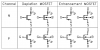
The components are:
R1: approximately 100k-ohm resistor
R3: current set resistor - (0.5/R=desired I)
Q1: small NPN transistor (such as: Fairchild 2N5088BU)
Q2: large N-channel FET (such as: Fairchild FQP50N06L)
LED: Luxeon
the Q2 isn't avaliable in my country
Wt other tansistors can i use?
eg. 2SX series
Can i use power mosfet instead of it?
Thx everyone~
**broken link removed**
The components are:
R1: approximately 100k-ohm resistor
R3: current set resistor - (0.5/R=desired I)
Q1: small NPN transistor (such as: Fairchild 2N5088BU)
Q2: large N-channel FET (such as: Fairchild FQP50N06L)
LED: Luxeon
the Q2 isn't avaliable in my country
Wt other tansistors can i use?
eg. 2SX series
Can i use power mosfet instead of it?
Thx everyone~
 hm: ,
hm: , 