Continue to Site

Welcome to our site!

Electro Tech is an online community (with over 170,000 members) who enjoy talking about and building electronic circuits, projects and gadgets. To participate you need to register. Registration is free. Click here to register now.

  • Welcome to our site! Electro Tech is an online community (with over 170,000 members) who enjoy talking about and building electronic circuits, projects and gadgets. To participate you need to register. Registration is free. Click here to register now.

Help needed in Relay/timer circuit

Status
Not open for further replies.

woodrufj

New Member
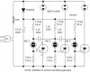
I'm kinda a novice at this circuit building. I'm trying to build a circuit to control a drag racing type start tree. I've built the timer delay as a series of cascading lm555 circuits per the third figure down in this link
**broken link removed**

Then I connected the outputs of of the lm555 to relays to drive the lights on the tree (along with some LEDs to see the circuit woking).

The circuit runs on 12VDC and the tree on 120VAC. I hooked the output of the lm555 across the coil of the relay. Then the Normally Open 'throw' of the relay connects the +120V to the light bulb, the -120V is always connected.

I know very liitle about the relays except for what they're suppose to do. The problem I'm having is the relays seem to stick on. Before I put the relays in the circuit worked perfectly lighting up the leds. Now the relays stick closed and it seems to hold the output high. Is there something I'm missing in hooking up the relays?

please help as soon as you can, people are expecting me to have this done on saturday.

Jay W
505/287 Dakota
 
The relay contacts are being welded together because the relay is not rated for the voltage and/or current of the 120 volt lamps. What is the manufacturer and model number of the relay?
 
How many 555s do have cascaded? Are driving the relay directly from the 555? Do you have snubber/clamping diodes on the relay coils?
Is this powered from a battery or transformer? Do you have filter capacitors?
It would be a big help if you could post your actual circuit.
 
There are better ways to do this than using 555s. Post your circuit and the timing you want to achieve, and we will be able to help more.

As for the lamps staying on, have you disconnected the 120 Volt lamps and replaced them with either low voltage ones or LEDs?

Have you measured the relay contacts to check if they are open when the relay is released and closed when it is operated?

Have you measured the voltage across the relay coil when it is operated and again when it is released

These types of tests will help you (and us) to deduce what the problem is.

Len
 
The best way to drive a relay from the output of a 555 timer is with a diode. Anode to pin 3, cathode to relay coil, other coil lead to ground or
negative rail. Only works for coil currents up to 200Ma as this is the ratings for the 555. If the coil requires more than 200Ma then a bipolar or power mosfet will work as a driver. With multiple 555's, erratic operation can occur unless each 555 has a bypass capacitor from pin 8 to the negative rail very close to the 555.
 
k7elp60 said:
The best way to drive a relay from the output of a 555 timer is with a diode. Anode to pin 3, cathode to relay coil, other coil lead to ground or
negative rail. Only works for coil currents up to 200Ma as this is the ratings for the 555. If the coil requires more than 200Ma then a bipolar or power mosfet will work as a driver. With multiple 555's, erratic operation can occur unless each 555 has a bypass capacitor from pin 8 to the negative rail very close to the 555.
What is the diode for?
 
Re: diodes

laroche73 said:
Ron, what's with this obsession about getting rid of diodes :) ?
I hate diodes! Did you know that diodes only pass current in one direction? Heck, a piece of wire is better than that!
 
In answer to Ron H's question. I didn't know for sure, when I posted the
original statment is was from experience from a number a years ago that I built a large quantity of time delay ckts for an automobile application. At the time I could only get the circuit to be reliable with the diode in series with the output when driving a relay.
Several moments ago I finished testing a 555 timer set up as a 2.5 second timer. Normal configuration with pin two pulled high with a 10k resistor. Grounding pin 2 caused the output to go high for about 2.5 seconds then it went low. I also connected a 1K in series with a LED on pin 3 to monitor the output. I also monitored pin 3 with an oscilloscope.
I tested 4 different manufacturers 555 timer chips. This the results.
A NE555P by Texas Instruments, without the diode the output would not return to 0 and there were oscillations present on the scope. With the diode the relay would deenergize after the 2.5 seconds.
A NE555N by STM worked fine with or without the diode.
A HA1755 manufacturer unknown would not work right with or without the
diode.
A TS555CN by STM did not supply enough current when the output was high to energize the relay. In fact the output dropped to about 5V.
In every case the timing was tested with out the relay as a load and just
the LED and resistor. The circuit performed like it should.
The relay had a resistance of 120 ohms for the coil. I had a 0.1uF capacitor from pin 5 to ground and a 47uF electrolytic from pin 8 to ground. I did use about 13 volts for VCC to overcome the diode and circuit losses to ensure the relay got 12 volts to the coil, even thou I know that relay's will generally pull in a slightly less than rated coil voltage.
So at this point ,I think I am half right, sometime you need the diode and sometimes you don't.
It just goes to prove even thou an IC is marked 555, it's guts may me different between manufactures.
 
relay stick on

hi,

since 120v bulbs are used, how about using triacs.
 
It's hard to argue with success (or the lack of it). Did you also have a diode across the coil, anode to GND?
 
After I posted my test results and failed to mention the diode across the relay coil, I figured someone would ask if I had a diode across the coil.
Yep it was there. Anode to ground. I even checked the diode to make sure it was good.
 
You can change the timing with larger capacitors.

Here is the modified drawing.
 

Attachments

  • sequence_mod.jpg
    sequence_mod.jpg
    30.7 KB · Views: 234
Status
Not open for further replies.

Latest threads

New Articles From Microcontroller Tips

Back
Top