Hey guys,
I'm doing a project on wireless notice board, and my codes are in assembly language
1. The wireless module is zigbee, and it's from pc to PIC,
2. The display is dot-matrix and data will be taken from EEPROM to be displayed
3. Only one way communication using USART from Zigbee to PIC6f628A
4. PIC will receive new data whenever available from ZigBee and store in EEPROM
5. The PC will be sending data through a ZigBee transmitter to the receiver.
So, currently I've got my display unit to work and everything, and can display 128 characters. All of which is pre-loaded into the EEPROM.
I'm having trouble with the communications part. How do I use USART to receive a data string and store into EEPROM one byte at a time? Plus I don't want to do the polling method.
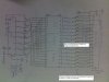
Attached is the codings that i've written.
1. The New + new table file is working fine and i need to embed the USART part into it
2. The Usart RC file is the one I've written for serial communication with ZigBee.
The code should work as: Displaying out data from EEPROM and when new data is received, it will take it and store into EEPROM and then start displaying all over again. Please help. Thanks
I'm doing a project on wireless notice board, and my codes are in assembly language
1. The wireless module is zigbee, and it's from pc to PIC,
2. The display is dot-matrix and data will be taken from EEPROM to be displayed
3. Only one way communication using USART from Zigbee to PIC6f628A
4. PIC will receive new data whenever available from ZigBee and store in EEPROM
5. The PC will be sending data through a ZigBee transmitter to the receiver.
So, currently I've got my display unit to work and everything, and can display 128 characters. All of which is pre-loaded into the EEPROM.
I'm having trouble with the communications part. How do I use USART to receive a data string and store into EEPROM one byte at a time? Plus I don't want to do the polling method.
Attached is the codings that i've written.
1. The New + new table file is working fine and i need to embed the USART part into it
2. The Usart RC file is the one I've written for serial communication with ZigBee.
The code should work as: Displaying out data from EEPROM and when new data is received, it will take it and store into EEPROM and then start displaying all over again. Please help. Thanks