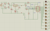
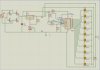
I made a regulated variable power supply with an output of 0-30V and 1.5A max. I want to put a voltage level indicator using a LED. I saw a sample in a book with a bipolar junction transistor and a zener diode but i cannot fully draw the circuit.
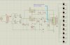
Please help me to design a circuit of this when every 3V from the output of power supply 1 LED will turn on. Then when 30V from the output, 10 LEDs will turn on.
Thank you in advance.
Please help me to design a circuit of this when every 3V from the output of power supply 1 LED will turn on. Then when 30V from the output, 10 LEDs will turn on.
Thank you in advance.