Continue to Site

Welcome to our site!

Electro Tech is an online community (with over 170,000 members) who enjoy talking about and building electronic circuits, projects and gadgets. To participate you need to register. Registration is free. Click here to register now.

  • Welcome to our site! Electro Tech is an online community (with over 170,000 members) who enjoy talking about and building electronic circuits, projects and gadgets. To participate you need to register. Registration is free. Click here to register now.

Help me understand this transformer hook up, please

Status
Not open for further replies.
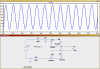
The second schematic shows a ground at the bottom even though that circuit is part of the live line side of things.

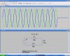
The first schematic seems to be conceptually in order though. I think C7 could be considered an optional component but I have seen quite a few SMPS with a small snubber capacitor between the primary and secondary circuits just the same.

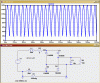
You find them in every circuit I've ever seen, so I wouldn't call them 'optional' - I imagine it's probably crucial to their noise performance?.
 
Yea I am not sure about that myself. I don't typically see them on manufactures suggested schematics for SMPS's but I do see them fairly often on the ones I take apart. Many times they are in parallel with a high ohm resistor or two, sometimes even going directly to the two main AC lines, as well so I suspect its all part of a static bleed off or other secondary protection system.
 
I started to simulate this circuit and the filter, but Spice can't find the transformer, and when I tried to upload the .asc file so I could post it here, it doesn't show up, nor does it with windows explorer, but when I look for it with the spice open command, it shows up but has a lock on it, can any one explain this? and can anyone tell me how to get the transformer circuit to work.
Thanks
Kinarfi
 

Attachments

  • Untitled.png
    Untitled.png
    16.2 KB · Views: 133
Perhaps using two inductors would suffice being he program sound like its confused about what purpose that its supposed to serve in the circuit.

Examples like this are just one of the many reasons I have never cared for using simulator programs.
 
Are you using LTSpice? Where did you get the transformer library? Is the library in the "sub" folder? You can use two inductors if you define the mutual inductance, and give it a value.

There are LTSpice experts here, but I don't know if they are reading this thread.
 
Hi again. Here is an easy way to model your filter. The line "K1 L1 L2 1" defines the mutual inductance for the two inductors. I just used the ".op" button to enter this line ( far left on the tools bar )
 

Attachments

  • line_filter.JPG
    line_filter.JPG
    194.3 KB · Views: 123
  • line_filter.asc
    783 bytes · Views: 90
From your schematic, I think the library does something identical to my circuit on post #26 just above. Only they used 30mH and I used 30uH, I think.
 
Actually, my circuit gives me an error and quits working, one thing I was trying to confirm is that the voltage across C4 is 170 vdc and the other thing I wanted to accomplish was to get my sim to sim, Oh well, onward and upward.
Thanks for the help and thanks for the input.
Kinarfi
 
What I"m not getting is, if your circuit won't simulate, why not just use mine that does simulate, and make any changes you need???
 
Yea I am not sure about that myself. I don't typically see them on manufactures suggested schematics for SMPS's but I do see them fairly often on the ones I take apart. Many times they are in parallel with a high ohm resistor or two, sometimes even going directly to the two main AC lines, as well so I suspect its all part of a static bleed off or other secondary protection system.

Yes, it's partially to prevent a high static charge building up on the output.
 
What I"m not getting is, if your circuit won't simulate, why not just use mine that does simulate, and make any changes you need???
Tried yours and it ran to 3.4% and then it had to much to do and stayed there but kept processing.
Thanks,
kinarfi
 

Attachments

  • line_filte-2r.asc
    1.5 KB · Views: 104
hi,
Both circuits simulate ok for me.

would you please attach your .asc file, and which version are you using, would you mind trying the one in post #23 also, I attached mine,
Interesting, on the .asc from post 32, if I put the ground ref anywhere but either side of the voltage source, it runs in no time at all, but stops at 3.4% done.
Thanks
Kinarfi
 

Attachments

  • post4.png
    post4.png
    76.1 KB · Views: 117
  • Draft2.asc
    1.7 KB · Views: 100
Last edited:
hi,
In your sim that version of the TRAFO is not included in the trafos.lib, so I cannot run it.

Using the LTspice ind2 to make up the transformer, it runs OK.

Same applies to post #23

EDIT:
Plot is top of C1
 

Attachments

  • 000esp01.gif
    000esp01.gif
    37 KB · Views: 142
  • line_filte-2r.asc
    1.9 KB · Views: 132
Last edited:
Thanks Eric, that little trick of adding the 1 meg resistor works great. I still have lots to learn about spice & I'm learning it slower than I like, but learning. I do appreciate your help.
Kinarfi
 
Status
Not open for further replies.

Latest threads

New Articles From Microcontroller Tips

Back
Top