Electro Tech is an online community (with over 170,000 members) who enjoy talking about and building electronic circuits, projects and gadgets. To participate you need to register. Registration is free. Click here to register now.
Welcome to our site! Electro Tech is an online community (with over 170,000 members) who enjoy talking about and building electronic circuits, projects and gadgets. To participate you need to register. Registration is free. Click here to register now.
hmm...you may get better results if you post it in the 'need homework solutions' section of this forum (better known as the 'trash can').
I'm sure everyone on here has time to sit around and do your homework for you...I could see giving up alittle bit of my time if you had some specific questions reguarding the hw, but to just ask for full solutions is rediculous.
I'm even getting "plz help me do my homework" pm's from the kid.
I told him to ask his teacher but he said that isn't allowed. I guess the teacher is just a high-paid babysitter. :cry:
Heres a little help so you can understand the problems and help you solve them yourself.
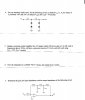
8 ) This is a filter. The gain of the filter is -(Feedback impedance)/Input impedance. At low freq, Reactance of cap(1/2*pi*FC) is high, so all current goes through the smaller 10M, hence gain = -10M/100k. At high freq, reactance of cap is low so Gain becomes - Reactance/100k. As freq increases Reactance decreases, so Gain gets smaller. It passes low freq, and not high freq. The freq at which it cuts off is 1/(2*pi*10M*0.01uf). Multiply your input 2V by the Gain at the freq your interested in, and you'll get the output waveform.
4) First work out which way is current is flowing in the arrangement when the input is at 3 different values, -10v, 0v, and 10v, then use ohms law to work out voltage drops, remember voltage across a forward biased diode is 0.7V.
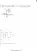
5) NPN transistor with a resistor on the emitter and collector, Gain is -Rc/Re. Bias the collector so its midway in the power supply to get maximum swing. So quiescent current is (Vcc/2)/(Rc). Couple the input with a capacitor, and resistor to ground, this acts like a high pass filter with cut off 1/(2*pi*R*C).
7) Op amp negative feedback works to keep the inputs equal. So if +ve input is at ground, -ve input will also be at ground. Input impedance of a circuit is impedance to ground the input signal "see's".
I find it curious how at the bottom of the first page it says "ELECTRONICS FINAL EXAM" and he says he's not allowed to ask his teacher for help... I wonder why :lol:
I hate to be mean, but did it occur to you that if you can't do ANY of those simple problems after taking the class, then you're going to be COMPLETELY confused when you have to take the next set of electronics classes?
Now some hints.
8. Assume the amp has very high gain.
Thus Vout = Zf/R Vin.
If you have learnt Laplace Transforms, then use them otherwise use calculus.
9. Is the Schmitt Trigger to be made using discrete parts or an Op Amp?
If the latter, then insert a feed back resistor from the output to the + input.
Connect a voltage divider to the + input. The input signal goes to the - input.
To determine the resistor values, you will need to solve a simulataneous equation.
Choose one resistor eg. set the feed back resistor to say 100 k, and solve the SE for the other 2.
Hint, use Thevenin's Theorm.
To set the output low to 1 Volt, use a voltage divider.
If it is to be a discrete ST, then I suggest you look at a book such as "Pulse, Digital & Switching Waveforms" by Millman & Taub.
It may be in your school's library.
11. An up/down 4 bit binary counter such as the 4516 would be a good choice.
You will also need something to remember whether the counters are counting up or down.
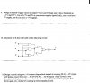
10. Write down the Boolean expression for the output of each gate.
eg. the expression for top AND gate is A2. A0 obviously.
The NAND is (A2 . A1)' where ' = bar.
So the output of the top OR gate is A2. A0 + (A2 . A1)'.
The Boolean for the XOR is A.B' + A'.B and for the XNOR A'.A' + A.B.
7. You need to determine the feedback voltage.
So you have to determine the transfer function of the feedback network. Use Kirchhoff's laws.
You could then use McMillman's & Thevenin's Theorms at the input of the amp to determine the error voltage.
im glad that at least somebody has had the decency to actually help the lad, afterall this is a electronics forum not a discussion of weather or not somebody deserves help or not.
It doesnt matter what he wants help for. get off your high horse
This site uses cookies to help personalise content, tailor your experience and to keep you logged in if you register.
By continuing to use this site, you are consenting to our use of cookies.