Ωhello guys
iam eletronic student ....currently i doing project with audio amplifier and LED.
i need to design a 0.5w audio amplifier with mute and volume control....the design should allow user to select two different bandwidth....selected choice must be indicated visually using LED...the power supply is +- 12V ...the leval of baseband signal is 250mv pk to pk at 1khz...
components should be used ...MicroA741. TDA7052A, regulator (LM78, L05), transistor 2N2222......
my group was able to design a circuit for our topic...we think there could be some minor faults in ckt.we are supposed to use only 1bandpass filter..and v should not use it for music.now the main problems in our ckt are:
*only two switches must be used,but in our ckt we don't knw which one 2 omit as there are 3switches.
*what is supposed to be done in between the frequency supply and the music's BJT?whether a resistor or some other device to be used there?
*when we test our ckt,do we need to test part by part(op-amp by op-amp)or we can directly patch up the whole things and test for the output?
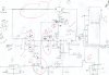
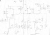
we have attached two ckt diagrams with this post..the one with red circles was done by us(which is 2 b corrected)
If the other one is more accurate and workable than ours..pls try 2 modify it for us.
pls kindly reply to me ASAP..it would be really helpful if do this favour for us. Thanks in advance
iam eletronic student ....currently i doing project with audio amplifier and LED.
i need to design a 0.5w audio amplifier with mute and volume control....the design should allow user to select two different bandwidth....selected choice must be indicated visually using LED...the power supply is +- 12V ...the leval of baseband signal is 250mv pk to pk at 1khz...
components should be used ...MicroA741. TDA7052A, regulator (LM78, L05), transistor 2N2222......
my group was able to design a circuit for our topic...we think there could be some minor faults in ckt.we are supposed to use only 1bandpass filter..and v should not use it for music.now the main problems in our ckt are:
*only two switches must be used,but in our ckt we don't knw which one 2 omit as there are 3switches.
*what is supposed to be done in between the frequency supply and the music's BJT?whether a resistor or some other device to be used there?
*when we test our ckt,do we need to test part by part(op-amp by op-amp)or we can directly patch up the whole things and test for the output?
we have attached two ckt diagrams with this post..the one with red circles was done by us(which is 2 b corrected)
If the other one is more accurate and workable than ours..pls try 2 modify it for us.
pls kindly reply to me ASAP..it would be really helpful if do this favour for us. Thanks in advance
")
