Continue to Site

Welcome to our site!

Electro Tech is an online community (with over 170,000 members) who enjoy talking about and building electronic circuits, projects and gadgets. To participate you need to register. Registration is free. Click here to register now.

  • Welcome to our site! Electro Tech is an online community (with over 170,000 members) who enjoy talking about and building electronic circuits, projects and gadgets. To participate you need to register. Registration is free. Click here to register now.

Help me identify dc power supply parts and design a schematic

Status
Not open for further replies.

FideBladeWorks

New Member
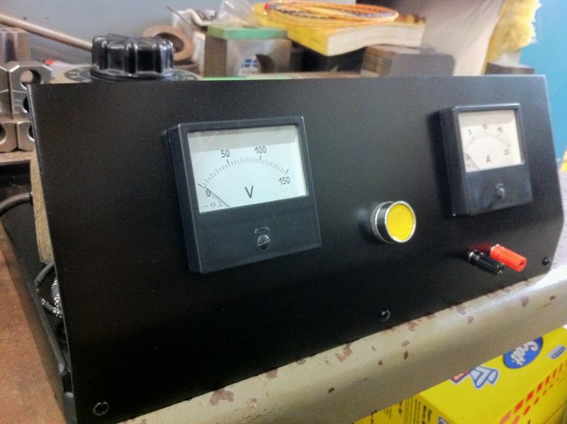
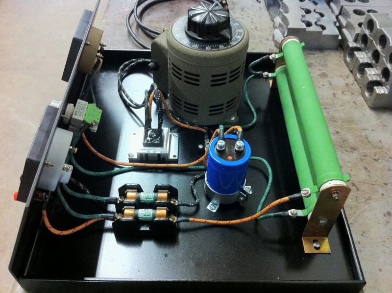
Hey all, this is my first post since returning to this forum after many years, excited to hopefully be learning here consistently and working with electronics more often. I have a very basic knowledge of how electricity works and the function of basic components. As a knifemaker which is what i do as my main occupation i would like to build a variable dc power supply for anodizing titanium, and thats where i need your help. I hope to make a pretty exact copy of another homebrew power supply that ill picture below, and i know the most necessary components are the variac, capacitor, and bridge rectifier, but i need help identifying the other parts that were used, their purpose, and making a schematic so i can begin this build. I plan to use a variac 0-130v with 5amp max and need help deciding what ratings i need to look for as far as the bridge rectifier and capacitor goes as well as for the the other parts such as displays and fuses, not to mention i have no clue what those large green cylinders are. I thank you all in advance

JoeAnodizer1.jpg


JoeAnodizer2.jpg
 
Odd design: It doesn;t look like the ammeter is hooked up to me. Assuming 120 VAC and you don't have one in front of you.
top bottom, left right,
DC ammeter (does't look like it's hooked up)
red/blk binding posts
Fuseblock and holder
Power resistors and bracket
Capacitor and clamp: probably 5000 uF at 400 VDC or therabouts.
An industrial switch with at least one contact block (The green thing)
A full wave bridge rectifier (probably 400 to 600 PRV at 25 Amps) mounted on a heat sink. A light film of silicone grease is used to improve thermal contact;
Terminal block - behind the capacitor
Voltmeter
Variac

Comments:
The green things are wire wound resistors, probably 200 W or so. My guess is the design allows two current limiting resistors. The right lugs can be swapped. One of the resistors essentially does nothing.

An ammeter is usually a micro-ammeter that is made to measure amps by converting it to read voltage across a shunt (typically (50-100 mV max) with a resistor. They can read directly.

Aside:
Some of the ebay digital meters put the shunt in the ground connection. That's probably not a good idea.


it's close to this: http://mrtitanium.com/anodizer.html

The green switch might select the two current limiting resistors rather than being power.

WHAT I DON'T LIKE ABOUT THIS DESIGN.
1. everything is open.
2. There is no isolation: i.e a 120:120 Isolation transformer.

For some reason the plating industry likes to call these things rectifiers.
 
This one https://www.bmisurplus.com/products/47078-xantrex-xfr100-12-dc-power-supply-0-100v-0-12a is very nice, but expensive Not quite 150 V. I've used that series.
I think it has a wide range line voltage input. It would need to be verified.

This https://www.bmisurplus.com/products/25083-sorensen-dcr150-18b-dc-power-supply-output-0-150v-0-18a one is a heavy supply, but more affordable, but it's operation is in the 240 V range. This general ERA power supply was really good for reliability. Lots of ripple, but that doesn't matter for you. We had about 10 in this series and they all developed
the same fault at the same time. The PCB electrolytic caps had to be replaced and I did them all.

The Constant current mode is generally used for plating/anodizing. The bigger the surface area, the more current you need.

--

With an isolation transformer https://toroid.com/Home/Product-Details/ProductID/50 and a Variac. your looking at almost $300.00 anyway unless you find something surplus. The medical version is better. These guys make nice stuff. They did a custom one for me in the 80's.
 
The capacitors will always have printed on them their capacitance and voltage rating.
That label is perhaps facing the Variac and you did not capture it.
 
It's a really nice looking build but the disconnected ammeter is a bit of a mystery. Maybe the photo was taken before it was complete - in which case it may actually have a lid which is not shown. If that is the case I would expect there to be some sort of window for the variac.
Anyway, it looks like you have all the information you need, though considering it has no isolation, maybe it's just me but using a ground leakage detector seems a poor substitute being dependent on a good ground connection, when you can never be 100% certain yours is correct/adequate.
 
Status
Not open for further replies.

New Articles From Microcontroller Tips

Back
Top