Continue to Site

Welcome to our site!

Electro Tech is an online community (with over 170,000 members) who enjoy talking about and building electronic circuits, projects and gadgets. To participate you need to register. Registration is free. Click here to register now.

  • Welcome to our site! Electro Tech is an online community (with over 170,000 members) who enjoy talking about and building electronic circuits, projects and gadgets. To participate you need to register. Registration is free. Click here to register now.

Help me figure out how these LEDs are configured in this light.

Status
Not open for further replies.

fastline

Member
So I am looking at LED lighting. I know most of China can't be honest with their ratings or specs so I am resorting to taking things apart and testing. What I have here so far is "electrically" the lights perform close to as-advertised. What I am trying to do is figure out how they are driving the LEDs.
Here is what I have so far.
Driver output rating is 38VDC, 2.57A
Tested under full lighting load, 35.6VDC, 2.57A
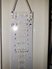
Each driver runs 168 diodes which are configured in "zones" and each zone has 12 diodes. Each zone has 2 parallel pairs that are in series, so 6 diode drops. There are NO resistors on the boards unless there is something hidden in the wafer, but I don't think so.

I have attached a pic of how the LEDs are driven. I believe them to be SMD3030, and measurements are at least consistent with that.

Ultimately I am just trying to figure out how they are driven so I can get a better idea of life and real world lumens. I will probably buy a lux meter and do more testing but just trying to get things on paper for now. It sucks that I cannot just use the data sheets but too many just lie and I don't want to light my building twice.
 

Attachments

  • 20200102_174539 mod1.jpg
    20200102_174539 mod1.jpg
    207.2 KB · Views: 119
Last edited:
The driver is a constant-current supply, providing a maximum voltage of 38 VDC. The LEDs bias the constant current supply to the sum of the series Vf (forward voltages).

As a simple example, support three series LEDs with a Vf of 3.3 volts are driven by a constant current supply. The bias voltage across each LED will be 3.3 volts, and across the string will be 9.9 volts.

Enough groups of parallel LEDs must be used to divide the current in each group into something reasonable for the LEDs. Suppose 10 well-matched LEDs are connected in parallel, and each LED can handle 20mA max. A 200mA constant current supply will deliver 200mA to the parallel group, equally divided between them.

Note: LEDs connected in parallel must be well matched to share current equally. If they are not well matched, some will draw more current and die quickly.
 
I have always been told that parallel of LEDs is not a real great idea, but that was before the modern COB days. Is manufacturing or sorting good enough these days that this is less a concern? I would think discrete parallel would be the only right way where each diode is fed from a common power supply, and each has their own resistor? I realize this method is not very main stream with LED lighting companies as I think it just adds complexity and I think the end goal is to ensure total failure so new equipment must be purchased. I am trying to pay close attention to how these lights are built to see who does it best.

I think what is most common is over driving the diode chips, which will certainly impress on initial purchase, but will not last. I am also noticing a deficiency in thermal management. In the case I am testing in this thread, the chassis is specified as Aluminum, but its actually stamped steel, and they are installing the PCB strips against the painted steel finish, so thermal transfer will not be good at all.

I know in my research and test data that thermal management is key to long life LED lighting.
 
Looking at that board layout, I'd guess it's driven by AC with a current limit.

The "parallel" LEDs are probably opposite polarity so one bank work on one half cycle and the other bank on the other cycle.
That avoids any matching problems with parallel pairs.

The heatsinking is via the large areas of copper between each pair of LEDs - most of the board area is covered in copper.

Can you try a multimeter on diode test (or a 9V battery and 470 Ohm resistor) across one LED and see if two light with it one way, or one half of each pair lights with each polarity?
 
Status
Not open for further replies.

New Articles From Microcontroller Tips

Back
Top