Continue to Site

Welcome to our site!

Electro Tech is an online community (with over 170,000 members) who enjoy talking about and building electronic circuits, projects and gadgets. To participate you need to register. Registration is free. Click here to register now.

  • Welcome to our site! Electro Tech is an online community (with over 170,000 members) who enjoy talking about and building electronic circuits, projects and gadgets. To participate you need to register. Registration is free. Click here to register now.

help in a simple PWM driven power transistor

Status
Not open for further replies.

barbababa

New Member
Hi!

I am completely failing to design a simple
circuit for PWM driven transistor to
control the current in a load. The voltage
to the load should be 30V and current
passing through it about 4 A. The load
should be connected to ground.
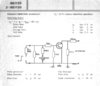
Something like the attached image perhaps...

Huge thanks for any help!
 

Attachments

  • Capture.JPG
    Capture.JPG
    48.2 KB · Views: 235
Is that load really 1.47 megohm? If so why are you driving it with a large power transistor?

Also the transistor in operating as an emitter follower so the load voltage can never be greater than the generator voltage minus about 0.7V.
 
I don't really know what you want to do:
Here is an example of getting 8A at 50% of the time for an average of 4A.
To simplify things I have the PWM "IN" hanging from the +12V supply.
Is this where you want to go?


upload_2014-2-15_10-44-27.png
 

Attachments

  • upload_2014-2-15_10-44-1.png
    upload_2014-2-15_10-44-1.png
    5.4 KB · Views: 200
Hello,

huge thanks for the answers. The only way I got the above circuit to work, was to add an extra
transistor 2n3055 to the gate as shown in the image. Is there anyhow to get rid of the falling
time of the output voltage pulse?

Thanks again!

Capture.JPG
 
Try a 10k pull-up resistor between Q5 base and the 30V rail. You may also need a similar pull-up for Q1 base.
A 3055 is overkill for Q4.
 
It's a bit unclear as to exactly what you want to do. In pst #1 you talk about a 30 volt supply and a 4 amp load then the example has a load resistor of 1 megohm.
Then in post #4 you ask about switching times(fall time) and alec t is suggesting a pullup resistor. He has identified the main problem with your circuit and that is that there is no means for the base circuit charges to be removed QUICKLY from the base/emitter region.
The 2N3055 is an old transistor design and was as common as insect pests when it was released. I looked for a data sheet but could not find what I want.
For your application as a switching transistor switching a 4 amp load, you need to have the data sheet to see the test circuit for achieving the specified switching times and the required level of base current.
I have the data for a BDY20 which was Philips number for this device. The attached file is pdf.
When one designs a switching transistor circuit it is imperative that the manufacturers recommendations are followed. The data sheet shows that the cutoff base current is the same value as the forward base current, and is one tenth of the collector current. Ic = 4 amp; Ib=-Ibm=400 mAmp. To achieve this requires a base current bias voltage of -2.8 volt applied through the 11.1 ohm resistor. This is the TEST CIRCUIT but it is the way that thte switching performance is determined. Also, this is for a resistive load.
the data sheets I got from the net showed some data for switching inductive loads. The parameter is called 'Sustaining Voltage'. You dont say if your load is inductive or resistive.
In a practical design, you would attend to the base drive by means of DC bias of the driver, or you might use a parallel CR circuit in the base drive to give the ability to suck out the charge carriers from the base region and put that charge into the capacitor in parallel with the series base resistor. The design of the drive arrangement for a TV line output stage might be helpful for your understanding.
I guess that your use of the 2N3055 is based on the fact that you have them or can get them cheaply. I can relate to that.
The 2N3055 has a 15 amp peak current rating so it should be OK for your application.
So unless you can be more specific about your application, then much of the advice you get may be hard to comprehend.
I designed a small speed controller for a spray unit pump and used a 2n 3054 as the switch. That thing ran at about 4 kHz. The controllers used on battery drills is a nice way to get a well designed variable speed controller for up to about 3 to 4 amps.
I hope my comments are helpful.
 
Status
Not open for further replies.

Latest threads

New Articles From Microcontroller Tips

Back
Top