Continue to Site

Welcome to our site!

Electro Tech is an online community (with over 170,000 members) who enjoy talking about and building electronic circuits, projects and gadgets. To participate you need to register. Registration is free. Click here to register now.

  • Welcome to our site! Electro Tech is an online community (with over 170,000 members) who enjoy talking about and building electronic circuits, projects and gadgets. To participate you need to register. Registration is free. Click here to register now.

HELP! ID this part.

Status
Not open for further replies.

fastline

Member
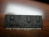
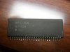
We have found this to be the failing component of a multi voltage DC power supply. This little daughter board is going to prove very tricky to try and remove the coating to get at the components. The chip is undoubtedly proprietary. The OEM of the machine this goes in is out of business. The OE of the chip is in Japan and I can find no support at all for it.


I have been told it might be an op amp but I am really not sure as of yet.

Ideas? We need this thing running a week ago so I need to make a decision like now if we need a different power supply or if we can figure this chip out. There is one identical to it in the circuit that is most likely good as it is showing voltage outputs. This one does not. Not sure if we could compare the two but that might be a serious challenge.
 

Attachments

  • SDC10986.JPG
    SDC10986.JPG
    1.8 MB · Views: 185
  • SDC10985.JPG
    SDC10985.JPG
    1.8 MB · Views: 164
You're going to have to remove that coating to see the components and traces. Guessing with that many pins would be futile.
 
Last edited:
I agree with Nigel.
Usually hybrid thick films have laser-trimmed resistors. Attempting to remove the coating would most likely scratch those resistors. Even if you managed to remove all the coating without damaging anaything, and find the defective semiconductor, most likely the device would require re-calibration, something you cannot do.
 
On a thick film hybrid, you print resistive paste with a silkscreen. The resultant bulk resistor tolerance is quite wide, and its value is well below the target value.
Then you take your circuit into a specialized fixture, which measures the variable you may want to trim (voltage, current, frequency, etc). A laser starts to cut extremely fine traces into the bulk resistor, increasing its value. This continues until you reach your variable's target value.

The important thing about this procedure, is that the actual resistor value is not that relevant. What matters is the variable you are actually trimming.
 
I guess what I was asking is basically if this technology was used 20 yrs ago? There is a darkened line in one place where I have cleaned down to the PCB. Not sure if there is an easy way to determine if this would have lasering or not. I know these chips cannot be bought so trying to do what I can if it could work.
 
Status
Not open for further replies.

Latest threads

Back
Top