Continue to Site

Welcome to our site!

Electro Tech is an online community (with over 170,000 members) who enjoy talking about and building electronic circuits, projects and gadgets. To participate you need to register. Registration is free. Click here to register now.

  • Welcome to our site! Electro Tech is an online community (with over 170,000 members) who enjoy talking about and building electronic circuits, projects and gadgets. To participate you need to register. Registration is free. Click here to register now.

Help - How to power my project ?

Status
Not open for further replies.

ItsMike

New Member
Hey guys,
I'm working on a project here and i'm having problems figuring out the best way to power it.

My project needs two voltage levels: 12v and 5v:
The 12v line should power a DC motor (took apart from a kids ride-able atv toy) the motor consumes about 1A when running, dunno about peak current on start up though.

The 5v line should power all the electronics - a pic micro couple of shift registers and 16 high power leds (at about 25-30mA each) = total of 500-600mA.

I have got my self a couple of AC to DC adapters:
A laptop's adapter which outputs: 16.5v and 4.5A.
And some router's adapter which outputs: 7.5v and 1A.

I already got a couple of 317's and 7805.
I was planning on using one 317 to get 12v for the dc motor and the 7805 for the electronics but if I use the laptop's supply a lot of power will be wasted on heat.
(16.5-12)*1+ ≈ 5w
and
(16.5-5)*0.6+ ≈ 7w

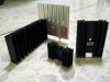
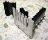
I've found some heatsinks lying around but I don't know their specifications (pics attached).

I guess I would either have to use the two AC-DC adapters to minimize the voltage drop across the voltage regulators or do something crafty with those heatsinks, maybe use couple of power supplies in parallel with the multi TO220 heatsink, or add a fan.

Any suggestions how should I power the project ?
 

Attachments

  • IMG_0514.JPG
    IMG_0514.JPG
    111.6 KB · Views: 140
  • IMG_0515.JPG
    IMG_0515.JPG
    150 KB · Views: 130
12 and 5 volts? Just off the top of my head, this looks like the perfect place to use an old computer power supply (ATX). I just got finished making my "bench power supply" from one. Supplies +12V at [lots of] A, same w/5V. Well regulated, too. Probably available for free. Tons of web pages out there showing how to make the conversion (really simple: basically connect one signal [PWR_ON] to ground).

Oh, and contrary to what these DIY instructions all say, I didn't need to add a dummy load resistor to make it work.

The biggest problem with these kind of conversions is the fact that there isn't any way to limit current or voltage (beyond the built-in limiting); without a way to put a set-point on the current, that powersupply will happily supply whatever is wanted or needed, until your circuit is toasted. That isn't to say they aren't useful for those on a budget, or for those needing such a supply; but the issue is something to be aware of.

Unfortunately, high-current adjustable multi-tap bench power supplies are anything but inexpensive...sigh.
 
The biggest problem with these kind of conversions is the fact that there isn't any way to limit current or voltage (beyond the built-in limiting); without a way to put a set-point on the current, that powersupply will happily supply whatever is wanted or needed, until your circuit is toasted. That isn't to say they aren't useful for those on a budget, or for those needing such a supply; but the issue is something to be aware of.

Well, maybe our questioner here would be OK with just using a fuse or two, which would eliminate the problem of toasting the circuit (at least it would give him overcurrent protection, and I wouldn't worry about overvoltage too much with a regulated computer PSU).
 
Last edited:
I would either use an ATX PSU as suggested and fuse it or I would just go buy one of these and run it into a full wave bridge rectifier something like this then filter it with several capacitors. I would run the motor on the unregulated DC, I doubt the motor will care much and then shove a LM7805 in there with more filtering for the PIC. Oh yeah, I would also fuse the latter.

Ron
 
Well, maybe our questioner here would be OK with just using a fuse or two, which would eliminate the problem of toasting the circuit (at least it would give him overcurrent protection, and I wouldn't worry about overvoltage too much with a regulated computer PSU).

For running a motor, that would probably be ok, but I have yet to find a sub-1 amp fast-acting fuse (maybe such things exist as an SMT part?). An over-current detection circuit can act upon small currents and very quickly, likely much quicker than any fuse. That doesn't mean you can't burn something out, but it's likely that you won't be causing a fire if you do. I have a small bench-supply (it was really an educational supply) that has dual outputs, one is fixed (5 volts regulated DC @ 1A), the other is adjustable from 0-25 volts, .01-1A (it also has a weird 14 volt AC output protected by a small breaker). It's nice to be able to set the voltage to what you need and the max amperage you're wanting, and if you exceed it, it shuts down instantly. When you need to protect against going beyond 150 mA, it's not a problem.

If there were an easy way to add such overcurrent protection to a modded PC PSU, it would make the beast much more versatile...
 
Status
Not open for further replies.

New Articles From Microcontroller Tips

Back
Top