Hi All, excuse the newbyness of this question, however I was wondering if some of you might be able to help.
at the moment I have a remote controller that controls a valve in my car exhaust but due to the crappy design of the remote the battery inside keeps coming loose.
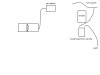
what I was thinking of doing was to make a hard wire switch using the chip board inside the remote and hooking it up to a 12V source inside my car (ie. car stereo power cable) - refer picture.
Basically the valve i nthe exhaust has 3 modes, open full - half open and closed. what type of switch would be appropriate to use and how would it work into the diagram i've drawn up?
does what I've drawn A: make sense & B: seem feasible?
Any help appreciated
Ben
at the moment I have a remote controller that controls a valve in my car exhaust but due to the crappy design of the remote the battery inside keeps coming loose.
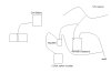
what I was thinking of doing was to make a hard wire switch using the chip board inside the remote and hooking it up to a 12V source inside my car (ie. car stereo power cable) - refer picture.
Basically the valve i nthe exhaust has 3 modes, open full - half open and closed. what type of switch would be appropriate to use and how would it work into the diagram i've drawn up?
does what I've drawn A: make sense & B: seem feasible?
Any help appreciated
Ben