Continue to Site

Welcome to our site!

Electro Tech is an online community (with over 170,000 members) who enjoy talking about and building electronic circuits, projects and gadgets. To participate you need to register. Registration is free. Click here to register now.

  • Welcome to our site! Electro Tech is an online community (with over 170,000 members) who enjoy talking about and building electronic circuits, projects and gadgets. To participate you need to register. Registration is free. Click here to register now.

Help fix benchtop power supply MP-3086)

Status
Not open for further replies.

spitso

Member
Hello all

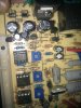
Recently blow up my MP-3086 benchtop powersupply i bought from jaycar, due to back emf from a tesla coil.
It normally has a max output of 31v 3amp, but now it stays at like 50v but no current flow. (2n3055 transistor has been replaced and same goes with shunt regulator aswell as lm358 ic and UA741CN ic)

would anyone have a schematic diagram for board model number AQD7.820.501
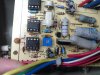
or even if you have this powersupply could you state the resistor value for r17(show in picture above blue pot), or even take a photo of your board and share it.

Thank-you
Jordan
 

Attachments

  • P10-09-10_17.55[02].JPG
    P10-09-10_17.55[02].JPG
    1.5 MB · Views: 581
  • P10-09-10_17.55[01].JPG
    P10-09-10_17.55[01].JPG
    1.4 MB · Views: 966
  • P10-09-10_17.55.JPG
    P10-09-10_17.55.JPG
    1.4 MB · Views: 618
I know this is old, but this is the only post that relates to the exact same PSU as mine that i've found.
How did you go in the end fixing this? if you got it working, do you know what the impedence is between positive and negative terminals when its switched off?

my resistor in place of r17 has a value of 480ohms while in circuit. i can try and get a camera to take a pic if you want me to.

I've identified the following sensitive components that i intend to replace.
2n3055
lm358 ic
ua741cn X 3
shunt regulator? is that the kbu808 bridge rectifier
N j20 TIP41C
L7812CV

PROB DONT NEED TO worry about these - on front board for the lcd display.
um7812
lm7806

also bought a transistor tester from peak electrical for a good price. apparently it works in circuit too, i hope this helps.
 
Last edited:
yea my bench top power supply is still sleeping haha. really havnt tried

yea if you could get a photo of that resistor so i can see what resistance value it is, would be much appreciated.

Yea i highly recommend replacing the 2n3055, once my power supply stuffed up and i replaced that transistor it fix it up perfectly.
Also ive blown soooo many lm352's and ua741cn's so make sure you have many handy just in case.

might have to get myself one of those transistor testers, would be very handy, as i made a homemade one which can just test the basics.

hope you figure whats wrong with yours. when you do lets us know how you went
also, what are your symptoms?
 
this is it - https://www.peakelec.co.uk/acatalog/jz_dca55.html
Ive attached a pic. of the board to.

how have you blown this thing up so many times? :)
I blew mine up by connecting it to charge a battery while running a bedini motor.

also, when you say you replaced the shunt, do you mean the bridge rectifier (kbu808) or another part?

i have a feeling there's a big fat diode hidden across terminals i might have to replace too. do you know anything about that one?

my symptoms are, when i place a meter across the terminals for voltage i get nothing. if i set the current to 150ma, and connect a 12v 100ma incandescent bulb while turning up the V dial, i get nothing, and the display reads 0v.

before that point, when i was connecting it to try and charge some battery, i got a dead short with the battery, and sparks going everywhere. thats why i want to know what the resistance across the terminals is supposed to be when off. could you do me a favor and measure your resistance there? even if its in a busted state? i have a feeling a dead short is not supposed to be there.
 

Attachments

  • IMG_20110614_230306.jpg
    IMG_20110614_230306.jpg
    842.6 KB · Views: 458
Thanks a lot, this thread has reminded me that I still had a dead power supply down in the garage, and inspired me to fix it.
(It was a 741 op-amp)
 
i identified 1 cracked 1n5408 diode last night. gonna go replace that today cos i only have 1n5404's. its was shorted both polarities.
 
i replaced the diode, and there was no short anymore connecting the meter leads to the terminals in either way. good news.

i used my dca55 to test the 2n3055 transistor at the back, and it said it was ok.

i fired up the power supply, and it worked. powered a 12v bulb fine for a few minutes. then i switched over to charging a 12v battery @ 13V, current limited to 700ma (the c20 rate of the battery).

all looked fine and dandy for a few minutes when suddenly white light and a burning sound came out of the side of the power supply. christ, thats never happenned before. switched it off and pulled it open again.

There appears to be a small cap blown on the circuit board. it is connected across the two ac rails that come from the transformer, then through 2 relays, then into the bridge rectifier. the cap is across the input to the bridge recifier. I have no idea why. because normally any signal smoothing is done with a cap on the output of the bridge rectifier. and its a tiny cap, so i dont know how it would fullfill that purpose even though its in parallel with the transformer, so it might be a resonant/filter of sorts. i know nothing about those guys.

is anyone able to chime in here on anything else i should look at? what might be a problem?

its strikes me as odd because before i identified a cracked diode on the dc output. but this cap has burst into flames on the ac input to the bridge rectifier, probably already stepped down from 240v to something like 36v. I don't understand the connection between these two events.

unless some how the shorted dead diode damaged the cap before. im stabbing in the dark.

in any case, i dont think replacing the cap is going to solve the cause. i fear its just a symptom.

@spitso: do you think you could tell me the value of the cap im talking about? it is c5 on the board. mine has been rendered unidentifiable.
 
Last edited:
sorry been away study for uni exams :(

wow sounds like your really making some progress.
checked c5 for you and its a 104 ceramic cap, which i believe is a value of 100nanofarads.

hope everything works out. keep updated of your status
 
i checked the 2n3055 with my dca55 meter, and the hfe was in the middle of all my others lying around, so pretty sure we can say that one's ok.

those 100nf caps are available in a 250v version, so i might get one of those. is it possible to blow a 250v cap with 240v or less? if so, how?
 
Im no expert and someone correct me if im wrong but i think that 100nf cap would just try and filter out even smaller ripples of voltage to give you a really "clean output", if that ripple was at a high enough voltage it could blow the capacitor up. Which i think may have cause the problem. Were you using the bedini motor at the time the cap blow? as it could be possible that the motor produced back emf spikes which caused the damage.

Just a theory as these power supply's obviously don't like back emf, considering mine was destroyed running a tesla coil.
 
the meter was only about 50 or 60 AUD, well worth it. without it, i wouldn't be able to diagnose transistors that amplify too much without maybe a proper test circuit.
I've bought replacement 100nf 50v caps so ill put those in tonight.

when the cap blew, psu was connected to charge a 12 battery with 700ma of current at about 13v.
the hfe of the 2n3055 was in about the 150 region acording to the dca. thats outside of the spec sheet which says 20-70.
i tested my other 4x 2n3055's i had lying around and they were all outside of the range on the spec sheet too, up to maybe 275!
so i thought, bah spec sheet musnt be right. but went into jaycar just then and tested 5 transistors in the store, and they were all within the spec range. means 5 transistors are actually broken too, including the one in the psu. so ill replace that too.
 
well the 100nf caps in the same package that blew up dont go up to 275v. more like 50v.
besides, it is on the other side of the transformer so it would be more in the region of 36v ish.
even the 100v packages are much bigger, so it cant be those.

hopefully a 50v will be correct. so ill replace that, and replace the transistor with one in the right hfe range. ill keep my meter attached next time i turn it on to see what level the ac voltage before the rectifier gets to. i need to get one of those little dso nano scopes. a good excuse.

feels like im treating symptoms still and not the cause.
 
It's been running smoothly for 10 minutes now. fingers crossed.

I measured the ac voltage before the bridge rectifier when it was on, and with the voltage set to max on the front panel it reads about 42VAC, which is below the 50V rating of the cap i put in there. must have been some sort of spike or a dodgy cap that caused it to fry. thanks for telling me the value of that guy spitso, wouldn't have been able to do it without you.

i think replacing that dodgy 2n3055 was wise because the other had an hfe of 155 or something. well out of the spec range. I wouldn't pick this without that awesome meter. I have no idea how to measure the condition of the regulators without making a circuit for them though.

Thanks everyone.

Can anyone tell me what the purpose is of the filament wires in a transformer?
 
got it working!!! bloody excellent!!
Great work mate.
no worries for the help, glad i helped.

I think i might re-attempt to fix mine after exams are over.
Might fiddle around with the main 2n3055 transistor, ive replaced it with ones i bought from ebay, had no idea about the doggy hfe untill now so i might just buy one from jaycar.

update us if anything else happens with your powersupply
 
will do man.

I bought my 2n3055 from jaycar, and i tested 6 in the store and all were in the rated hfe range. what city are you in? I'm in adelaide at the moment.
 
looks like i might have to buy one of those meters you got, as a dmm is all i really have.

Im in Melbourne.
 
Ok looks like a i have a bit of time tonight to spare on trying to fix my power supply.
Just a quick question queglay, the 3 wires going to the 2n3055 tranistor (thin green, thick yellow, thick blue). What wires go to what transistor lead?
(i left the transistor unsoldered and now ive forgotten)

My guess is green to base, blue to emitter and yellow to collector?

cheers
 
Status
Not open for further replies.

Latest threads

Back
Top