Continue to Site

Welcome to our site!

Electro Tech is an online community (with over 170,000 members) who enjoy talking about and building electronic circuits, projects and gadgets. To participate you need to register. Registration is free. Click here to register now.

  • Welcome to our site! Electro Tech is an online community (with over 170,000 members) who enjoy talking about and building electronic circuits, projects and gadgets. To participate you need to register. Registration is free. Click here to register now.

help designing a cicut to pass only certain ttl pulses

Status
Not open for further replies.

youicide

New Member
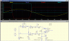
Let me start off by saying that I am not an EE I'm a chemist of sorts, more of an instrument person. We have a source of +5V TTL pulses coming at 80 MHz and we only want to pass ones when a sine sync voltage is below a certain level or above a certain level and we need to be able to switch between the two, hopefully programatically (or with a control voltage from a DAQ or whatever). Also we need the voltage pass level to be adjustable. I apologize if this is a bit confusing but the attached figure should give an idea of what I need. If someone could point me in the right direction or if they gave me a design I could throw 20 bucks their way as it would save me a lot of hassle.

I don't work for a company, I'm at a large research university (Emory).

Thanks
 

Attachments

  • sync-figure.png
    sync-figure.png
    97.6 KB · Views: 298
You could use an LM339 analog comparator to generate the gate signal. One differential input of the comparator is the Sync signal and the other is the trigger level voltage. The LM339 has four comparators in one package so you could use one to generate the upper gate and one to generate the lower gate by inverting the input connections to one of them. The desired gate output could be selected by a dual AND-OR gate controlled by a digital signal. This feeds another AND gate to gate the 80MHz signal.

Do you want the voltage pass level adjustment to be programmable also? If so you could use a DAQ for that.

Edit: This question should have been put in the Electronic Projects Design/Ideas/Reviews forum. You would likely get more responses there.
 
Last edited:
Thanks for the info. Would the attached (rather crude) diagram work? Basically when I want to pass pulses when the sync voltage is high I keep -Vpass really low so the sync never goes below it and set +Vpass to the voltage above which I want ttl pulses to pass through. For passing ttl pulses when the sync is low I could set +Vpass to a high value and -Vpass to the voltage below which ttl pulses are passed. Does this make any sense?


If someone could move this to the proper forum that'd be good.
 

Attachments

  • ttl-pass.png
    ttl-pass.png
    36.1 KB · Views: 263
Last edited:
The LM339 needs a pull-up resistor to V+ for proper operation.

That circuit should work as you described.

Your scheme requires two separate trigger level values and mine requires only one but also more logic gates, so that's the tradeoff.
 
Last edited:
The output of the LM339 is an open collector transistor with emitter to common so it needs a load (pull-up) resistor from the output to V+ to generate the high logic level. It's value mostly depends upon the risetime speed you need. 1k ohm is a good value.

Just add one resistor from the LM339 paralleled outputs to V+.

Which reminds me of an error in my previous post. Connecting the outputs in parallel makes for a wired-AND connection -- both outputs must be high for the output to go high (either output low generates a logic low). Thus you need to reverse the input connections on both the comparators and add an inverter (or use a NAND gate instead of an AND gate) at the LM339 output for proper operation.
 
Last edited:
You didn't understand my entire post.

You need to reverse the plus and minus connections to each comparator input.

I also made another error.:eek: 
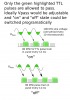
The gate should be changed from an AND to a NOR gate (not NAND as I previously stated).
 
Here's the skeleton of one possibility. U1 is a unity-gain inverter for the 100kHz sine wave. U2 and U3 compare respectively the inverted sine and the sine against an adjustable threshold Vpass. The comparison output pulses are level-shifted and fed to inverters U6 and U7 to sharpen the pulse edges. The sharpened pulses, together with a polarity-switch signal which selects whether the positive or negative half-cycles of the 100kHz signal are used, gate the 80MHz pulses in U4.

Edit: Simulation shows that the main challenges will be circuit response time (we're talking nanoseconds) and precision in determining at high speed when the threshold is exceeded. So experimentation may be needed to select the optimum high-speed op-amp/comparators. The threshold signal Vpass could be inverted instead of the sine wave.
 

Attachments

  • Gating80MHz.gif
    Gating80MHz.gif
    24.6 KB · Views: 259
  • Gating80MHz0.asc
    3.9 KB · Views: 257
Last edited:
Thank you for the design!

If by response time you mean the time it takes for the 80 MHz pulses to be passed after the 100KHz signal has reached a certain level, it doesn't matter to0 much. 1 microsecond response would be enough although smaller is better. What program did you use to simulate the circuit?
 
The circuit was simulated with LTspice, a free Spice type analog simulator from Linear Technology. I strongly recommend anyone designing or building circuits download a copy and learn to use it. The initial learning curve can be a little intimidating but the tutorials are quite helpful and it's well worth the effort. I never build a circuit without first simulating it to catch the obvious bugs and errors.
 
OK so figured out all I need is line to go high when sine wave goes above a threshold, like the teal trace in the figure that was posted in the first page. Will the attached diagram work for that? I intend on setting Vpass-low to a very high level then setting Vpass-high to a threshold level so the system will go high when the sine is above Vpass-high. Vice versa when I want to make the line go high when the sine voltage is below a certain level.

I seem to not be good with ltspice. I cannot figure out how to get the program to recognize 74hc.lib so it always gives me warnings and blank spaces when I load the diagram on the preceding page.
 

Attachments

  • afm-sync-circut.png
    afm-sync-circut.png
    34 KB · Views: 242
I cannot figure out how to get the program to recognize 74hc.lib
You need to add the directive '.inc 74HC.lib' to the dwg.
Your dwg doesn't show a -V generator.
Shorting the outputs of the two gates together is not a good idea.
 
Status
Not open for further replies.

Latest threads

New Articles From Microcontroller Tips

Back
Top