Russell Hayes
New Member
Hi Guys,
This is my first post here although I have been lurking around here and other electronics forums for a while now.
I am in the middle of a small project to build a simple wired control device to remotely control the focus ring of a camera lens and need a little help. The device consists of a hand held box with a ‘control knob/wheel’ that, when rotated, proportionally drives a standard RC servo with a gear attached. The gear then engages to another gear fixed to the lenses focus ring, thus, focus can be controlled remotely. There are similar commercial products available like the images below:
**broken link removed****broken link removed****broken link removed**
The heart of the device is a small commercially available servo controller, which comes shipped with a 10K potentiometer. The servo is connected to this controller; also 4x AA batteries are connected to power the system.
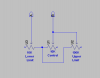
3 wires from the controller are then connected to the 10k potentiometer and, as the pot is rotated, the servo turns proportionally and in a linear fashion to the control knob pot. So far so good! Below shows how this is wired up:
**broken link removed**
The servo can rotate 180 degrees. When the main control knob is turned fully left, the servo is at 0 degrees. When the main control knob is turned fully right, the servo is at 180 degrees. Perfect!
Now, my goal (and where I’ve hit a hurdle) is to add two ‘end point limiters’ into the mix. By this I mean 2 extra control knobs/potentiometers, which reduce the travel of each end of the servo. So when these ‘limiters’ are both set to ‘full’ the servo rotates its full 180 degree travel when the ‘main knob/wheel’ is rotated from end to end.
If the ‘left limiter’ is turned, the servo only travels from 0 degrees to 100 degrees (depending on setting), from example. Or, if the ‘right limiter’ is turned, the servo only travels from 80 degrees to 180 degrees, from example. If both are turned, the servo only travels between 80 to 100 degrees, for example.
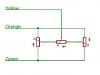
I have tried a simple wiring of 3 potentiometers, like below:
**broken link removed**
This works but the problem is that the servo no longer turns proportionally to the control knob. When the knob is turned, it starts slow and then accelerates as the pot is turned. It is not linear to the control knob.
Does anyone know why this would be or how to solve it so that the servo rotates proportionally and in a linear fashion to the control knob pot?
This is my first post here although I have been lurking around here and other electronics forums for a while now.
I am in the middle of a small project to build a simple wired control device to remotely control the focus ring of a camera lens and need a little help. The device consists of a hand held box with a ‘control knob/wheel’ that, when rotated, proportionally drives a standard RC servo with a gear attached. The gear then engages to another gear fixed to the lenses focus ring, thus, focus can be controlled remotely. There are similar commercial products available like the images below:
**broken link removed****broken link removed****broken link removed**
The heart of the device is a small commercially available servo controller, which comes shipped with a 10K potentiometer. The servo is connected to this controller; also 4x AA batteries are connected to power the system.
3 wires from the controller are then connected to the 10k potentiometer and, as the pot is rotated, the servo turns proportionally and in a linear fashion to the control knob pot. So far so good! Below shows how this is wired up:
**broken link removed**
The servo can rotate 180 degrees. When the main control knob is turned fully left, the servo is at 0 degrees. When the main control knob is turned fully right, the servo is at 180 degrees. Perfect!
Now, my goal (and where I’ve hit a hurdle) is to add two ‘end point limiters’ into the mix. By this I mean 2 extra control knobs/potentiometers, which reduce the travel of each end of the servo. So when these ‘limiters’ are both set to ‘full’ the servo rotates its full 180 degree travel when the ‘main knob/wheel’ is rotated from end to end.
If the ‘left limiter’ is turned, the servo only travels from 0 degrees to 100 degrees (depending on setting), from example. Or, if the ‘right limiter’ is turned, the servo only travels from 80 degrees to 180 degrees, from example. If both are turned, the servo only travels between 80 to 100 degrees, for example.
I have tried a simple wiring of 3 potentiometers, like below:
**broken link removed**
This works but the problem is that the servo no longer turns proportionally to the control knob. When the knob is turned, it starts slow and then accelerates as the pot is turned. It is not linear to the control knob.
Does anyone know why this would be or how to solve it so that the servo rotates proportionally and in a linear fashion to the control knob pot?