Continue to Site

Welcome to our site!

Electro Tech is an online community (with over 170,000 members) who enjoy talking about and building electronic circuits, projects and gadgets. To participate you need to register. Registration is free. Click here to register now.

  • Welcome to our site! Electro Tech is an online community (with over 170,000 members) who enjoy talking about and building electronic circuits, projects and gadgets. To participate you need to register. Registration is free. Click here to register now.

Heater element controler design any improvements posible???

Status
Not open for further replies.

rjvh

New Member
Hi i am redesigning all my controls for solar heating equipment due to new compenents that are availible now here where i live

as before the watelevel indicater works fine and thanks for the help from this forum and some of his members

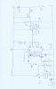
this design is to have several switch points in a tempature range for control of a booster heater element, solenoid supply/disharge valves, pump motor activation

heater element, pump and solenoid valves are all swiched by contactors or relais
as i have to make the interface in some cases with exsisting switch panels

i have build the design as shown in the shematic and it is now on my work bench for torchering puprpose and see where the weak spots are

please give me your coments

Robert-Jan
 

Attachments

  • TMP4.JPG
    TMP4.JPG
    168.2 KB · Views: 232
You shouldn't have the 22:mu:F capacitor directly connected to the output of the LM3914, as it could cause a very large current in the output that you are using.

You should put a resistor in parallel with the opto isolator input, in case there is some leakage current in the LM3914. 10k would do.

You should put LEDs and resistors on every output of the LM3914 so that you can see what is happening.

Your can use a PNP transistor instead of the opto-isolator. You would need to connect the PNP transistor to the +ve supply.

I hope this helps.
 
thanks for the coments I will try it out

the capacitor i need otherwise the relais doesnt swich at ones (it shatters without the capacitor and smaller than 22:mu:F)
but maby with the pnp transistor not necesary I will check it out

of course i will put leds on every output and on some outputs i need also to swich other relais

reason for not drawing them is that the shematic gets verry messy if i would draw them in (i should have writen that in my first post )sorry

Thanks Robert-Jan
 
Last edited:
Diver 300 thanks for your sugestions

i made it with a pnp (BC556) transistor and i could skip the capacitor from the LM3914 output and it worked without problems

still i can not understand why i needed that capacitor before to easy the swich behaivour of the relais

thanks

Robert-Jan
 
Status
Not open for further replies.

New Articles From Microcontroller Tips

Back
Top