Continue to Site

Welcome to our site!

Electro Tech is an online community (with over 170,000 members) who enjoy talking about and building electronic circuits, projects and gadgets. To participate you need to register. Registration is free. Click here to register now.

  • Welcome to our site! Electro Tech is an online community (with over 170,000 members) who enjoy talking about and building electronic circuits, projects and gadgets. To participate you need to register. Registration is free. Click here to register now.

Headphones, amplifiers, and virtual grounds

Status
Not open for further replies.

Sam Jelfs

New Member
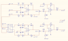
Hi all, I'm looking to build a headphone amplifier, based around the CMoy design (**broken link removed**). Quick question, the circuit uses a virtual ground, at 4.5vdc, is it still fine to connect the headphone ground to this?
Secondly, it is going to be built in a metal case, which in turn will be rack mounted, so the case will be earthed to the mains, so is it best to keep everything separate, isolating the switches, sockets etc from the case and linking them to the virtual ground, or to re-design the circuit to use a single supply rather than dual supply, and link the grounds to the case?

Hope that makes sense, if I get time later I'll draw the circuit up properly, not just pen-and-paper and post it up for comments.

Cheers

Sam J
 
No, just connect the headphones to battery 0V and use 220:mu:F coupling capacitor on the outputs.
 
In an equipment rack, use a power supply instead of a 9V battery that has a Mickey Mouse virtual ground. Then the power supply can have dual polarities and a proper ground for the circuit. Don't connect the circuit to the earth ground, let the input cable ground it to the ground of the source to avoid a ground loop. It is fine if the metal case is connected to the ground of the equipment rack.

A single supply will cause the circuit to make a loud POP when it is turned on and off.
 
It will emit a pop anyway due to C1.

To avoid the pop you could use a relay and a timer to connect the headphones a few 100ms after the power is applied.
 
I'm not to worried about the pops damaging my cans, as i'll be adding some volume / gain controls in so should be able to turn it down before turning on / off...

thanks for the comments everyone, any suggestions over power supplies? I'd rather not have "wall wart" style ones as my rack distro only has IEC outputs...
 
The POP will be extremely loud. It might damage your headphones or damage your hearing. The volume control adjusts the volume of the singnal, not the volume of the POP.

With a proper dual polarity supply, there is only a small CLICK.
 
Last edited:
What do people think to this circuit? it is essentially the CMoy circuit with his balanced-to-unbalanced circuit added to the front end. All grounds would be the ground of the left input signal, and isolated from the case.

What do people think to this power supply? PSU - linking the case to mains earth input?

Mods - do i need to move this / start this again in the projects forum now its more than just a quick question?

Thanks for all your help people :)

Sam J
 

Attachments

  • headphone-amp-1.PNG
    headphone-amp-1.PNG
    34.9 KB · Views: 699
I think the CMOY sucks ass. If the OPA2134 was suitable for a headphone amp then TI would market it as such. They don't. Stupid audiophiles popularized this because it is simple. Simple does not mean good.

You can build a *slightly* more complex circuit that is much, much better and has been around a long time. It uses an opamp (a 2134 would be great) to feed a pair of push-pull emitter followers (BD139/BD140 transistors). The transistors are biased using 1N4148 diodes and resistors. It is all very simple to understand.

**broken link removed**

The push-pull transistor pair itself would have quite a bit of distortion, but they wrap them inside the feedback loop of the opamp which compensates for all of it.
 
I dislike the LASKAR. It is only capable of 50mA on the -5V line, not 200mA like on the + side.

You could always use a single supply with a buffer like the old BUF634 biased at 1/2 VCC with 1% resistors to provide a virtual ground that would be capable of 250 mA of current. This is the best way to make a floating ground using a single supply.

https://focus.ti.com/docs/prod/folders/print/buf634.html

You can also use the BUF634 as a booster stage for the output of an opamp to make a good headphone amp. It is all detailed in the data sheet. This would be a simplified version of the way of doing it in the image above since the power stage is all contained in the buffer chip.
 
Last edited:
It's a headphone amplifer so he doesn't need much current.

A µA741 would do the job, especially if ihe stuck 100µF capacitors from the output to either side of the supply, that way it wouldn't be doing much at AC.
 

Attachments

  • Virtual Earth Low PWR.GIF
    Virtual Earth Low PWR.GIF
    4.1 KB · Views: 787
Some of these earbud headphones these days get down to 30 ohms, whereas Senn's and others can be 300. I just don't like using opamps for anything less than a kohm or so.
 
Above DC the two capacitors form low impedance paths to the supply, thus bypassing the output of the op-amp. At 20Hz they'll be about 80Ω each so the total earth impedance will be half that because they're effectively in parrallel so that's 40Ω and if you need a lower impedance then use larger capacitors.

It doesn't matter if the op-amp can only output a few mA because at AC it's not doing any work, C1 and C2 are powering the load. You only have to worry about the op-amp's output current at DC. In this case it's DC is only being used to bias the amplifier and the current is very small - no problem for the op-amp.
 
Last edited:
Status
Not open for further replies.

New Articles From Microcontroller Tips

Back
Top