Continue to Site

Welcome to our site!

Electro Tech is an online community (with over 170,000 members) who enjoy talking about and building electronic circuits, projects and gadgets. To participate you need to register. Registration is free. Click here to register now.

  • Welcome to our site! Electro Tech is an online community (with over 170,000 members) who enjoy talking about and building electronic circuits, projects and gadgets. To participate you need to register. Registration is free. Click here to register now.

Have layout, is this capacitor a problem for operation?

Status
Not open for further replies.

fastline

Member
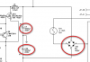
I need to fix an audio amplifier that went down over the weekend. No transient hit or overheat, just stopped working. All fusing is good and all components I have tested so far are good except the capacitor that is circled. It just looks like a drain to me and should not hold up operation but I am not sure. It connects to chassis ground.

There is a rack of 7 mosfets that are identical and all are testing fine so far. Main power caps look minty. Still trying to find the smoking gun here!

Thanks. I can post a pic of the board if that will help.
 

Attachments

  • FSR amp mod 1.pdf
    111.3 KB · Views: 311
Hard to tell without being able to measure around. It might be the cap. Also it's a good chance that at least one mosfet is became bad. Mosfets can be hard to tell if they're bad or not because they may fail under certain circumstances, t.ex they can short when Uds reach a voltage that is lower that maximum rated Uds.
 
That cap tested closer once removed from circuit but still at 10nf when it should be like 4 but I am guessing this is a low tolerance cap. Probably not my culprit...
 
After testing most everything on the board and deciding everything I tested was fine, I decided to throw it back in for testing and it worked! I did not push it but it powered up fine and responded to input the appropriate output. So I added the rest of my screws and was going to run it through some testing. I powered up again and immediately after hitting the power switch, I got a very loud, 60-100hz signal from the woofer. The kind of noise that makes you run for the power switch. Because the noise was instantaneous, I knew it was not waiting for power up from the preamp board, there was something dead wrong in the amp and that was confirmed after testing with a known good amp.

SOOO, clicking or popping noise went back to fine, then to super loud noise. I am wondering if this tone is actually line frequency or 60hz which might indicate the filter caps BUT all the caps look great and are 10yo. I think in every situation where caps have been bad, they show a sign. Any leads here? Controllers for the mosfets? caps? output or PS?
 
I would recomend to try check the power supply, rectifier diodes and caps (because of the humming sound).

Otherwise, a dead short in the amp could get the reason that powersupply failed - so then again, I beleive that the mosfets is the original source of fault.
 

Attachments

  • schematic_littlepartof.png
    schematic_littlepartof.png
    12 KB · Views: 262
New find..

I found that R30A (22 ohms) was either a bad solder weld or got hot but either way, it was suspect so when I went to test it, it fell off the board. I replaced the SM resistor with an axial lead of equal value. I was REALLY hoping I found the smoking gun and that would explain why it worked, then didn't BUT it did not fix my issue. I suspect that R30A and R30B would both have to go to kill the circuit.

Let me know if this could help point in a direction? I will review your pics. thanks
 

Attachments

  • FSR amp mod 2.pdf
    111.3 KB · Views: 239
Last edited:
I did removed the bridge originally and it bench tested fine though I did not apply power to it. I was going to remove the filter caps as well. My thought was that 60hz ripple is making to the driver, is that accurate? This noise certainly is about that range. Could the caps actually just go bad? They look minty and seem to test fine in the circuit. I can put a DMM and cap meter on them but no way to test ESR right now. Would my methods show the problem if there is one?

Would there be harm in powering the circuit in this condition? I would like to test some stuff on the board but I am guessing if the PW is bad, it could hurt other stuff if allowed to stay powered to long.
 
Status
Not open for further replies.

Latest threads

New Articles From Microcontroller Tips

Back
Top