Continue to Site

Welcome to our site!

Electro Tech is an online community (with over 170,000 members) who enjoy talking about and building electronic circuits, projects and gadgets. To participate you need to register. Registration is free. Click here to register now.

  • Welcome to our site! Electro Tech is an online community (with over 170,000 members) who enjoy talking about and building electronic circuits, projects and gadgets. To participate you need to register. Registration is free. Click here to register now.

Hardwired Logic - Please some help

Status
Not open for further replies.
Ello folks!

Today I need your help once again :) I'm studying hardwired logic and I have some problem understanding... well actually making the truth table.

**broken link removed**

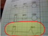
Sorry my webcam isn't very good. If you don't see well, the first line is BP1, BP2 and CR3
2nd CR3 BP3 and CR4 and 3rd is CR4 and SV1.

Now, when I look at it and want to make my truth tablem I struggle with CR4.

Does first CR4 = 1 when I touch nothing ? Because I see that the current will flow... BUT if the current does flow, well the second CR4 will then become open (will be 1).
Or is it the contrary ?

If I open the circuit in line 2, CR4 won't have power and then SV1 won't work, or is it that it will work only if I open the circuit in line 2 ??

I'm so confused. I'm sure it's pretty damn easy but at the moment it's a pain

thanks guys
 
The symbol in the bottom branch shows a bar across the contacts, which means that it is normally-closed (when relay coil CR4 is NOT energized).
This implies that the CR4 contact is OPEN when coil CR4 IS energized.
 
Ok so it means when I push Push-Button 1 and 2, the CR3 will open and then CR4 couldn't be energized and SV1 will be true.

Man, thanks a whole lot for comfirming this, I apreciate
 
Short circuit

Hi. It looks like a possible short circuit for me.

It's just like having a normally closed switch connected between any logic oputput and ground or supply voltage.

Please arrest me if I'm wrong - has been a couple of years since I did such kind of things.
 

Attachments

  • shorted.png
    shorted.png
    53.3 KB · Views: 261
Last edited:
Well,

CR3 = BP1 * BP2
CR4 = ^CR3 * ^BP3 = BP1 * BP2 * ^BP3
SV1 = CR4

That is, basically you can make it one step instead of three, as in your drawing.

But I'm still unsure og the function of SV1. First I thougth it was supposed to be some switch. But that wouldn't make any sens, would it?
 
So, basically it's a chain reaction from the top down to SV1.
If BP1 and BP2 are pressed, CR3 energizes. On the second rung, if CR3 is energized, CR4 de-energizes (or, CR4 is energized as long as CR3 is not) but will also de-energize if BP3 is pressed (since it's a NC pushbutton). On the third rung, SV1 will energize as long as CR4 is de-energized.
So, to generate a truth table: (1 is electrical continuity, not whether the button is pressed)

BP1 | BP2 | BP3 | CR3 | CR4 | SV1
------------------------------------------
0 | 0 | 0 | 0 | 0 | 1
0 | 0 | 1 | 0 | 1 | 0
0 | 1 | 0 | 0 | 0 | 1
0 | 1 | 1 | 0 | 1 | 0
1 | 0 | 0 | 0 | 0 | 1
1 | 0 | 1 | 0 | 1 | 0
1 | 1 | 0 | 1 | 0 | 1
1 | 1 | 1 | 1 | 1 | 0

Now, you mentioned something about optimizing this logic. Are there any requirements? Do you have to keep CR3 and CR4? can you change the type of switch?
 
So, basically it's a chain reaction from the top down to SV1.
If BP1 and BP2 are pressed, CR3 energizes....

Forget it, I just looked at again.
 
Last edited:
Status
Not open for further replies.

Latest threads

New Articles From Microcontroller Tips

Back
Top