Electro Tech is an online community (with over 170,000 members) who enjoy talking about and building electronic circuits, projects and gadgets. To participate you need to register. Registration is free. Click here to register now.
Welcome to our site! Electro Tech is an online community (with over 170,000 members) who enjoy talking about and building electronic circuits, projects and gadgets. To participate you need to register. Registration is free. Click here to register now.
Hi N,
I thought that PWM was the same however you look at it, and using a PIC HW was best.
I understood that the PIC HW PWMs are in pairs, for use as PUSH PULL, with allowance for a NULL POINT, but set as individual, only 4xCH they are simple PWM, but it appears not.
I will give it a bit more time, then revert to a previous program where 1-2ms is used.
Thanks.
PWM, as in a PIC, varies from 0 to 100%, with 0% Vss and 100% Vdd, with 1024 steps (depending on settings) - servo pulses vary from 1mS to 2mS or so, on a 20mS cycle time, so only gives about 50 steps if fed from PWM. Historically servos used PPM (pulse position modulation), not PWM.
I can probably write an example program tomorrow (in C) that should be easily convertible. I have a board with a 16F18446 setup on it that should be able to do it and should be easily convertible.
PWM, as in a PIC, varies from 0 to 100%, with 0% Vss and 100% Vdd, with 1024 steps (depending on settings) - servo pulses vary from 1mS to 2mS or so, on a 20mS cycle time, so only gives about 50 steps if fed from PWM. Historically servos used PPM (pulse position modulation), not PWM.
Yes, PPM is what I'm thinking. If a single CH PROCEDURE is set up to use the timer2 in the PWM section of the 18F4431 18.0 then cycle through each PWM PIN as PPM does. Does this seem feasable?
C
If you look at table 18-2 in the datasheet it has a lowest frequency for PWM as 3.9kHz at 1MHz clock frequency. You need 50Hz!!!!!!!!(at 40MHz) As I said, the PWM module cannot do servo pulses.
I can probably write an example program tomorrow (in C) that should be easily convertible. I have a board with a 16F18446 setup on it that should be able to do it and should be easily convertible.
If you look at table 18-2 in the datasheet it has a lowest frequency for PWM as 3.9kHz at 1MHz clock frequency. You need 50Hz!!!!!!!!(at 40MHz) As I said, the PWM module cannot do servo pulses.
No, I'm suggesting using one of the CCP modules with Timer1 (16 bit) to generate the signals at about 500nS resolution. Not sure what resolution you're getting out of timer2.
No, I'm suggesting using one of the CCP modules with Timer1 (16 bit) to generate the signals at about 500nS resolution. Not sure what resolution you're getting out of timer2.
Hi M,
Ok, but (I'm a bit out of my depth here), but I don't think CCP will do what I want, as there are only 2x of them.
Here is my old program, is this similar to what you mean?
C.
Code:
'servo test 27.07.2018

Define CONFIG1L = 0x00
Define CONFIG1H = 0x08
Define CONFIG2L = 0x1e
Define CONFIG2H = 0x00
Define CONFIG3L = 0x00
Define CONFIG3H = 0x83
Define CONFIG4L = 0x80
Define CONFIG4H = 0x00
Define CONFIG5L = 0x0f
Define CONFIG5H = 0xc0
Define CONFIG6L = 0x0f
Define CONFIG6H = 0xe0
Define CONFIG7L = 0x0f
Define CONFIG7H = 0x40

''''Define SIMULATION_WAITMS_VALUE = 1
AllDigital  'comparators off

Dim t1word As Word
Dim t0 As Word  'servo 0 ontime
Dim t1 As Word  'servo 1 ontime
Dim t2 As Word  '20ms - T0 - T1
Dim servo As Byte

Disable High
Disable Low

T1CON = %00011101  '1:2 -> Timer1 clock = 1MHz
T2CON = 0
T3CON = 0
OSCCON = %01111110  '8MHz

INTCON = %00000000
INTCON2 = %00000000
INTCON3 = %00000000
PIR1 = 0
PIR2 = 0
PIE1 = 0
PIE2 = 0

IPR1 = 0
IPR2 = 0
IPR1.TMR1IP = 1
RCON.IPEN = 1  'this MUST be included

TRISA = 0x2f
TRISB = 0x00
TRISC = %00000000
TRISD = %00001111
LATD = %00001111

TRISE.0 = 0  'TXD LED
TRISE.1 = 1
'TRISE.2 = DHT I/O

PORTB = 0
LATB = 0

ADCON0 = 0x03  'adc
ADCON1 = 0x09
ADCON2 = %10100100

T1CON.TMR1ON = 0

PIE1.TMR1IE = 1
PIE1.RCIE = 1
PIR1.RCIF = 0
'Hseropen 9600
'Hserout "Ready ", CrLf

TMR1L = 0xdc
TMR1H = 0xf0

Enable High
Enable Low

INTCON.GIE = 1
INTCON.PEIE = 1

t0 = 1000
t1 = 2000
t2 = 17000  '20000-t0-t1

servo = 2
t1word = 65534
TMR1H = t1word.HB
TMR1L = t1word.LB

T1CON.TMR1ON = 1

idle_loop:
Toggle PORTA.4  'some thing to do!
WaitUs 1000
Goto idle_loop

End

On High Interrupt
Save System

PIR1.TMR1IF = 0  'clear the TMR1 IF flag

T1CON.TMR1ON = 0

If servo = 2 Then
servo = 0
PORTB.0 = 1
t1word = 65535 - t0
TMR1H = t1word.HB
TMR1L = t1word.LB
Goto rtn
Endif

If servo = 0 Then
PORTB.0 = 0
PORTB.1 = 1
t1word = 65535 - t1
TMR1H = t1word.HB
TMR1L = t1word.LB
Endif

If servo = 1 Then
PORTB.1 = 0
t1word = 65535 - t2
TMR1H = t1word.HB
TMR1L = t1word.LB
Endif

servo = servo + 1
rtn:
T1CON.TMR1ON = 1
Resume
If you look at table 18-2 in the datasheet it has a lowest frequency for PWM as 3.9kHz at 1MHz clock frequency. You need 50Hz!!!!!!!!(at 40MHz) As I said, the PWM module cannot do servo pulses.
It's been discussed many times here over the years, and (if I recall correctly?) it's apparently doable by using interrupts to change the settings every pulse - or something like that.
It seemed rather complicated, and getting away from the nice simple operation which you'd hope you'd get from the PWM hardware.
The servo pulse system incredibly simple, as it is based on discrete component electronics dating back to the 1960s. You are probably assuming it to be far more involved than it is!
In the radio control system, the transmitter sends pulses triggered by a daisy chain of timers, each controlled by a joystick pot & triggering the next when it times out, and the sequence re-started every 20mS to 50mS or so. The times between the pulses are the pulse time for each servo in the system.
The radio receiver output feeds a shift register that passes a "1" bit through, moved along by each sequential timer pulse. The time each timer in the transmitter runs for, between 1 - 2mS, sets the duration of the pulse output at that stage of the shift register, so it controls one servo from each joystick pot on the TX.
When no pulses are received for a few milliseconds, it resets and waits for a new restart pulse, to trigger the first output again.
---------------
You are emulating that in software, shifting a bit along the pins on an output port.
You only need one free-running timer and one compare unit, plus a list (array) of time setting for each servo.
The spikes are equivalent are the sequence restart and then at compare match, where you shift the bit along the outputs and update the compare..
Just shift the bit through the port and add the duration of the required pulse for the appropriate servo, that the "1" is lined up with, to the counter present value and put that in the compare register each time a new compare happens.
That gives you up to eight independently-controlled times from a very simple loop sequence.
(You can also use an external shift register IC, just with two PIC pins to drive the data and clock inputs.).
Hi R,
Yes, as I already mentioned, I have this type of program. I wanted to use the PWM Hardware of the PIC, but have been advised that this is not a good idea.
As ususal, I won't simply stop trying the HW idea, but I'm slowly gojng off it. EDIT: I don't have this type of program, and it looks good.
C.
Hi R,
Yes, as I already mentioned, I have this type of program. I wanted to use the PWM Hardware of the PIC, but have been advised that this is not a good idea.
As ususal, I won't simply stop trying the HW idea, but I'm slowly gojng off it.
C.
Hi N,
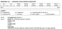
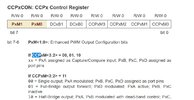
I started looking through the Microchip example, and came up against this:
Looking at both you can see that my PIC doesn't have the required CCP BITS.
I didn't want to change the 4431 PIC, but I looked for a PIC with 6x SERVO type outputs, and failed.
There is only so much time and effort, I'll make before giving in, and that up I think.
So back to square one, where I use my existing 1-2ms program.
Hi,
I've dug out the old program with 1-2ms
Had a quick test and with a slight change (Due to different old PIC) compiles an runs in the simulator.
I'll set up and test it with an actual SERVO, and see what happnes.
Cheers, C
There is another way to drive servo's with a pic. There is a pic with quite a few CCP modules.. But if I remember they only had three timers... I will check and see.
THEN!! I will make a module that you can call in oshonsoft... It might take a day or so. You problem may be getting hold of such silicone at the moment... pic18f23j13 has 7 CCP modules Which IS supported in the Oshonsoft pic18 IDE..
This site uses cookies to help personalise content, tailor your experience and to keep you logged in if you register.
By continuing to use this site, you are consenting to our use of cookies.

")