Electro Tech is an online community (with over 170,000 members) who enjoy talking about and building electronic circuits, projects and gadgets. To participate you need to register. Registration is free. Click here to register now.
Welcome to our site! Electro Tech is an online community (with over 170,000 members) who enjoy talking about and building electronic circuits, projects and gadgets. To participate you need to register. Registration is free. Click here to register now.
The R/C timing in Oshonsoft is made with software delays, so it blocks the processor.
I don't know if OP needs the PIC to do something else concurrently.
At least to read the input values is needed.
Hi I,
This is almost above my head but what I understand is the 18F4431 PWM PINS are in pairs, so where it looks like there are 8x there are only 4x. I was going to use the 4x for joysticks, and the 2x CCP controlled ones for other things, but I have been kind of talked out of this, in favour of the #45 CODE.
C.
The R/C timing in Oshonsoft is made with delays, so it blocks the processor.
I don't know if OP needs the PIC to do something else concurrently.
At least to read the input values is needed.
Hi J,
There will be a constant incoming of DATA from joysticks etc, that will go through some calculations in the main LOOP (Not yet thought about) that will constantly update the SERVO CODE/PINs.
Forgive me if the timings out but basic sucks... I tested on a sim and it seems to work.
Code:
Define CONFIG1L = 0x00
Define CONFIG1H = 0x02
Define CONFIG2L = 0x0e
Define CONFIG2H = 0x20
Define CONFIG3L = 0x1c
Define CONFIG3H = 0x9d
Define CONFIG4L = 0x80
Define CONFIG4H = 0x00
Define CONFIG5L = 0x0f
Define CONFIG5H = 0xc0
Define CONFIG6L = 0x0f
Define CONFIG6H = 0xe0
Define CONFIG7L = 0x0f
Define CONFIG7H = 0x40

//File:   servo_pwm_test_v2.C
//Author: robert jenkins

//Created On 09 May 2022, 09:45


//Better optimised version, more consistent Output timing And
//no timer Interrupt Or anything needed in main program section,
//beyond the initialisations.

//The main program loop can have delays Or wait loops,
//As Long As interrupts are never blocked.

#define CLOCK_FREQUENCY = 20
ANSEL0 = 0
ANSEL1 = 1

Dim index As Byte

Dim servo_times(8) As Word

Dim time_now As Word
Dim time_set As Word

Dim shift_reg As Byte

//With this timing, 1mS = 1000 counts;
//servo 1mS to 2mS = 1000 to 2000,
//with 1500 as mid point.


//For demonstration, I'm setting the servo times
//to various fixed values.

//Set them from your program as needed.


servo_times(0) = 1500  //Port bit 0, Mid position
servo_times(1) = 1100  //Port bit 1, Near min position
servo_times(2) = 1900  //Port bit 2, Near max position
servo_times(3) = 1300  //Port bit 3, Under mid position
servo_times(4) = 1700  //Port bit 4, Over mid position
servo_times(5) = 1200  //Port bit 5, etc
servo_times(6) = 1800  //Port bit 6
servo_times(7) = 1400  //Port bit 7

TRISC = 0  //Port C all outputs

T1CON = 0x31  //8:1, switch on

//Without an output pin defined, just an interrupt from CCP
CCP1CON = 0x02  //ccp_compare_toggle

//And enable the interrupts for the hardware used
//the reference for CCP1, so no time interrupt required.
PIE1.CCP1IE = 1
INTCON1.GIE = 1


//Main loop
loop:

    //Nothing needed here for servos, it's all in the CCP interrupt.
    //Rest of the program here onwards.


Goto loop

End

//INT_CCP1
On High Interrupt


    shift_reg = ShiftLeft(shift_reg, 1)  //Shift the bit left one place.
    //shift_reg = shift_reg + shift reg would do the same.
    LATC = shift_reg  //Write the shift register bits to the port

    //Increment index for next servo time value
    index = index + 1

    If index < 8 Then  //All servos already done?
        //No, do next servo

        //Set the duration for this output, as a new offset
        //from the last compare time.
        time_set = time_set + servo_times(index)

        CCPR1L = time_set.LB  //Write the compare time to CCP 1 register.
        CCPR1H = time_set.HB

    Else
        //No output needed as the port is already updated.
        //output_c(0); // Turn off all servo bits.

        //restarting the sequence.

        time_set = time_set + 1500  //add 1.5mS for the next interrupt
        //Update CCP
        CCPR1L = time_set.LB  //Write the compare time to CCP 1 register.
        CCPR1H = time_set.HB

            If index > 15 Then
                //15 * average 1.5mS = 22.5mS, a reasonable frame repeat time

                //Set up for a new sequence
                index = 0
                shift_reg = 1  //Set a bit that will be at port bit 0.

                time_now.LB = TMR1L  //Get the timer present count
                time_now.HB = TMR1H
                time_set = time_now + servo_times(index)  //And set the first duration
                LATC = shift_reg  //Write the shift register bits to the port
                CCPR1L = time_set.LB  //Write the compare time to CCP 1 register.
                CCPR1H = time_set.HB
            Endif
    Endif


Resume
A servo pulse is about 1mS maximum width, so 1uS resolution would give you 0.1% 'accuracy', which is more than you need, and much more than the accuracy of the servo.
Bit like your car speedo, do you really want it to read to the nearest 100th mile/hour
Hi I,
I'm amazed at your speed! I would have taken weeks, just shows the difference between skill and amateur.
Anyway, thatnks for the conversion, now it's readable, I could probably correct it, given time.
My first test, compiled ok, but in the Simulator, the INTERRUPT didn't fire.
I'm not at home at the moment, so perhaps not a fair test.
C
Absolutely, there are many ways to do it.
Single servos are dead simple in internal hardware, but then you need a compare unit each for pure hardware control - unless you reconfigure at each step?
The simplest multi-servo one is to use a separate shift register IC to make a hardware version of the above program - using a single CCP output as clock to move the bit along the register, to each servo o/p in turn, plus one pin for the data input to do the setup.
(The program is a software recreation of that setup, used in a project some years ago).
The external shift register gives the full accuracy of the internal clock running at whatever speed you can get without an overflow in less than 2mS.
Even the above software routine could run with a far higher timer clock, eg. 8MHz or even up to 32MHz, though that is pushing the time limits as the counter will overflow in just over 2mS.
Is there another hardware multi-servo method?? I'd be very interested in any possibilities!
Hi R,
As mentioned, I'm out of my depth, but there are 2x HW CCP timer PINS, and 4x PWM single PIN outputs. I haven't figured out how the 4x PWMs work or whether they can also use the same timer.
I looked for another PIC as suggested by 'I' but it's not practical to change from the 4431, so we're left with 2x and 4x.
My guess is your program + 'I' is the way to go.
C.
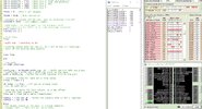
Hi I,
I ran the simulation for longer this time, and still no INTERRUPT.
My guess, is that the time is not setting, see WATCH VARIABLES in the image.
C.
Tested on Oshonsoft sim and the interrupt doesn't fire...
On Proteus it works as expected... The only issue I have is CCP1 is on PORTC2 and doesn't work.
If you use this micro, you'll have to swap to portb or loose this output
'18f4431 20mhz INT REMOTE PWM IR 100522 1900

Define CONFIG1L = 0x00
Define CONFIG1H = 0x02
Define CONFIG2L = 0x0e
Define CONFIG2H = 0x20
Define CONFIG3L = 0x1c
Define CONFIG3H = 0x9d
Define CONFIG4L = 0x80
Define CONFIG4H = 0x00
Define CONFIG5L = 0x0f
Define CONFIG5H = 0xc0
Define CONFIG6L = 0x0f
Define CONFIG6H = 0xe0
Define CONFIG7L = 0x0f
Define CONFIG7H = 0x40


//File:   servo_pwm_test_v2.C
//Author: robert jenkins

//Created On 09 May 2022, 09:45


//Better optimised version, more consistent Output timing And
//no timer Interrupt Or anything needed in main program section,
//beyond the initialisations.

//The main program loop can have delays Or wait loops,
//As Long As interrupts are never blocked.

Define SIMULATION_WAITMS_VALUE = 1  'Comment in for SIM out for PIC &
'Define CLOCK_FREQUENCY = 32
'Define SINGLE_DECIMAL_PLACES = 2

'At 20MHz, to figure a PWM frequency of 19.455kHz

#define CLOCK_FREQUENCY = 20
Define CLOCK_FREQUENCY = 20  'CHANGED &

ANSEL0 = 0
ANSEL1 = 1

Dim index As Byte

Dim servo_times(8) As Word

Dim time_now As Word
Dim time_set As Word

Dim shift_reg As Byte

//With this timing, 1mS = 1000 counts;
//servo 1mS to 2mS = 1000 to 2000,
//with 1500 as mid point.

//For demonstration, I'm setting the servo times
//to various fixed values.

//Set them from your program as needed.


servo_times(0) = 1500  //Port bit 0, Mid position
servo_times(1) = 1100  //Port bit 1, Near min position
servo_times(2) = 1900  //Port bit 2, Near max position
servo_times(3) = 1300  //Port bit 3, Under mid position
servo_times(4) = 1700  //Port bit 4, Over mid position
servo_times(5) = 1200  //Port bit 5, etc
servo_times(6) = 1800  //Port bit 6
servo_times(7) = 1400  //Port bit 7

TRISC = 0  //Port C all outputs
TRISB = 0  //Port C all outputs'CHANGED &

T1CON = 0x31  //8:1, switch on

//Without an output pin defined, just an interrupt from CCP
CCP1CON = 0x02  //ccp_compare_toggle

//And enable the interrupts for the hardware used
//the reference for CCP1, so no time interrupt required.
PIE1.CCP1IE = 1
INTCON1.GIE = 1


//Main loop
loop:

Toggle RD0  'Toggle LED
WaitMs 500

//Nothing needed here for servos, it's all in the CCP interrupt.
//Rest of the program here onwards.

Goto loop

End

//INT_CCP1
On High Interrupt


shift_reg = ShiftLeft(shift_reg, 1)  //Shift the bit left one place.
//shift_reg = shift_reg + shift reg would do the same.
'LATC = shift_reg  //Write the shift register bits to the port
LATB = shift_reg  //Write the shift register bits to the port CHANGED &


//Increment index for next servo time value
index = index + 1

If index < 8 Then  //All servos already done?
    //No, do next servo

    //Set the duration for this output, as a new offset
    //from the last compare time.
    time_set = time_set + servo_times(index)

    CCPR1L = time_set.LB  //Write the compare time to CCP 1 register.
    CCPR1H = time_set.HB

Else
    //No output needed as the port is already updated.
    //output_c(0); // Turn off all servo bits.

    //restarting the sequence.

    time_set = time_set + 1500  //add 1.5mS for the next interrupt
    //Update CCP
    CCPR1L = time_set.LB  //Write the compare time to CCP 1 register.
    CCPR1H = time_set.HB

    If index > 15 Then
        //15 * average 1.5mS = 22.5mS, a reasonable frame repeat time

        //Set up for a new sequence
        index = 0
        shift_reg = 1  //Set a bit that will be at port bit 0.

        time_now.LB = TMR1L  //Get the timer present count
        time_now.HB = TMR1H
        time_set = time_now + servo_times(index)  //And set the first duration
        'LATC = shift_reg  //Write the shift register bits to the port CHANGED &
        LATB = shift_reg  //Write the shift register bits to the port
        CCPR1L = time_set.LB  //Write the compare time to CCP 1 register.
        CCPR1H = time_set.HB
    Endif
Endif


Resume
Tested on Oshonsoft sim and the interrupt doesn't fire...
On Proteus it works as expected... The only issue I have is CCP1 is on PORTC2 and doesn't work.
If you use this micro, you'll have to swap to portb or loose this output
Hi I,
I've changed PORTC to B, and the INTERRUPT doesn't fire.
Here's my changes, in case I did it incorrectly. FIND '&' for the lines I changed.
If you want you can leave it with me and I'll go through it till I find the error.
C
A servo pulse is about 1mS maximum width, so 1uS resolution would give you 0.1% 'accuracy', which is more than you need, and much more than the accuracy of the servo.
Bit like your car speedo, do you really want it to read to the nearest 100th mile/hour
You completely missed the point. Back some time in the 80s (or 90s) I wrote a program to control a servo. It worked but the servo constantly "chattered". I eventually found that a 1uS difference in pulse width caused the "chatter". Repeatability is desired, accuracy irrelevant.
This site uses cookies to help personalise content, tailor your experience and to keep you logged in if you register.
By continuing to use this site, you are consenting to our use of cookies.