After reading this article some time ago, I really wanted to design something similar for myself in the form of an ankle bracelet. Now that I've completed a college course in digital system design, I can see how it would work, but I'm in the interesting position of understanding digital logic while knowing essentially nothing about managing current.
My design so far involves using a Dinsmore 1490 digital compass, and eight shaftless vibration motors. The compass has outputs for the four cardinal directions, and will output on N and E for NE, allowing it to detect eight directions. My plan is to take the 1490's outputs, send them through the appropriate AND and NOR gates, and send those outputs to the motors, so that whichever motor is facing north will vibrate, giving me a constant sense of which way is north. My power source will probably just be a 9V battery, unless something else makes more sense.
The only problem is, the 1490 takes a recommended 8-13 volts, where the motors take a recommended 2.5-3 volts, and I haven't the least idea what's the best thing to use to adjust the voltage. I've googled it, but I'm still mystified as to what to do. What do you recommend?
Edit: So, another hour or so of looking at things and all I've learned is that the stuff my class taught me only comprises a tiny bit of basic electronics and that I know nothing. Hopefully this is one of those things where someone more knowledgeable than me can look at this post and instantly name the one or two parts that I need. If not, I found someone selling a kit that would work just as well for me, though it's way more expensive than making this from scratch.
Edit 2: Completely overlooked the fact that the logic gates I'll probably use operate at 5V, so I'll need to adjust the voltage for that too.
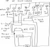
Edit 3: Here's a schematic, my apologies for the terrible quality.
My design so far involves using a Dinsmore 1490 digital compass, and eight shaftless vibration motors. The compass has outputs for the four cardinal directions, and will output on N and E for NE, allowing it to detect eight directions. My plan is to take the 1490's outputs, send them through the appropriate AND and NOR gates, and send those outputs to the motors, so that whichever motor is facing north will vibrate, giving me a constant sense of which way is north. My power source will probably just be a 9V battery, unless something else makes more sense.
The only problem is, the 1490 takes a recommended 8-13 volts, where the motors take a recommended 2.5-3 volts, and I haven't the least idea what's the best thing to use to adjust the voltage. I've googled it, but I'm still mystified as to what to do. What do you recommend?
Edit: So, another hour or so of looking at things and all I've learned is that the stuff my class taught me only comprises a tiny bit of basic electronics and that I know nothing. Hopefully this is one of those things where someone more knowledgeable than me can look at this post and instantly name the one or two parts that I need. If not, I found someone selling a kit that would work just as well for me, though it's way more expensive than making this from scratch.
Edit 2: Completely overlooked the fact that the logic gates I'll probably use operate at 5V, so I'll need to adjust the voltage for that too.
Edit 3: Here's a schematic, my apologies for the terrible quality.
Attachments
Last edited:
