Continue to Site

Welcome to our site!

Electro Tech is an online community (with over 170,000 members) who enjoy talking about and building electronic circuits, projects and gadgets. To participate you need to register. Registration is free. Click here to register now.

  • Welcome to our site! Electro Tech is an online community (with over 170,000 members) who enjoy talking about and building electronic circuits, projects and gadgets. To participate you need to register. Registration is free. Click here to register now.

Hall sensor VS. Current shunt resistor

Status
Not open for further replies.

adrianvon

Member
Hi,

I want to do a circuit which will stop the motor (12V DC) from working when a certain amount of current is exceeded (approx 2.5A). Now i am confused which type of current sensing component to use. Can someone give me his opinion on which component is most suitable ?

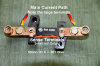
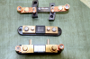
By the way, for the shunt resistor i was going to use the circuit linked below:

https://www.romanblack.com/current.htm

Thanks in advance.
 
Last edited:
And BTW is that called a Current Shunt Resistor or a current sense resistor ??

It can be called either.

For 2.5 A, I would say to use a resistor. With much larger motors, the power loss with a resistor can get very large and then a hall sensor is worth the money.

To keep the power loss low, you want to keep the voltage across the resistor small. Therefore I feel it is better to use a comparator or the DAC on the PIC. If you use a transistor as a comparator, the trip point depends on the temperature.
 
Screwed up the edit. Please see next post. :(

Ron
 
Last edited:
There are a number of ways to go about it. However, in the interest of economical I would run with Roman Black's simple and effective design. Just remember the Rshunt needs to be a very low value. I suggest this for a simple home brew solution. If I were doing this for a commercial application I may think slightly different and look at turn key off the shelf solutions but since you do not want to measure or read the current on a display I would use Roman's circuit. Works fine and will last a long time. :)

Ron

Just remember the current through Rshunt can't cause heating!
 
Hi,

Thanks for yor replies.

Just remember the current through Rshunt can't cause heating!


Why is that? isn't the 2.5A passing from Rshunt?

I also have some questions regarding Roman Black's circuit:

1) Is R3 use so that when the transistor is saturated, the supply will not be shorted to ground?
2) Why is R2 used ?
3) Does the base voltage of the transistor depend on the voltage coming from R2 and from the voltage coming from point A?

I will appreciate if someone can answer these questions.

Thanks.
 
Attached are a few images depicting some standard everyday current shunts. Since you mention:

Why is that? isn't the 2.5A passing from Rshunt?

If we think about it the shunt has a resistance. We pass a current through that resistance to get a subsequent voltage drop and measure that drop. For example a 10 amp shunt like the one pictured in one of the images outputs 50mV at 10 amps. We can pretty much figure therefore that .050 Volt / 10 Amps = .005 Ohm. So the current shunt is 5mΩ between the shown voltage pick off terminals. When we pass a current through the resistance of the shunt we do not want it getting hot and the resistance changing.

Shunts are standardized to deliver either 50 millivolts or 100 millivolts at their full rated current,
although there are times when other millivolt ratings are desired or other physical sizes or
configurations are more suitable for an application.

Since the shunt is a resistor which operates in a varying ambient temperature environment and generates heat whenever current flows through it, we must design the shunt resistance portion with a special metal alloy which has, essentially, a constant resistance value through its operating range. In addition to using a precision resistance alloy with a negligible temperature coefficient of resistance, the alloy must have a low resistivity in order to keep the self-heating to a minimum, and it must also have a low thermal E.M.F. against copper. A special shunt manganin alloy meets all these criteria, therefore, all our shunts are designed using this special alloy.

The key word in all that is the alloy manganin and the above quote was taken from here.

Roman's circuit is actually a pretty slick little circuit. We have the motor and the motors negative side with a shunt resistance, so the motor current passes through the current sense (Rshunt) providing a voltage drop. If we look at the +5 volts down through R2 and the Pot P1 we get to the voltage drop across the Rshunt. Roman points out to use a resistance that will drop 50 mV at your desired trip level. The pot allows some adjustment. The idea here is when there is 50mV across the shunt the base of Q1 will be driven high enough to turn it on. C1 is in there to remove the bumps and oppose any small voltage changes (noise or slightly changing motor current). Normally with Q1 off the collector of Q1 would be 5 volts as a result of R3. However, when Q1 turns on (saturation) the collector voltage will drop to about 0 volts (ground) with the 5 volts now dropped across R3. Thus when the PIC sees a logic low we tell it to do something. :) Really a slick simple current sensing circuit on the cheap.

Again, I am sure you see the reason for my comment as to Rshunt not heating up to where the resistance would change. If that resistance were to change it creates problems as you can see.

That Make Sense Now?

Ron
 

Attachments

  • 50 Amp Shunt.png
    50 Amp Shunt.png
    1 MB · Views: 432
  • Shunts1.png
    Shunts1.png
    1.1 MB · Views: 369
Last edited:
Thanks Reloadron for explaining.

Can i use a resistor as the one in the attached image instead of the one you have attached? and what are the main advantages of using shunt resistor instead of hall effect sensor for this application?
 
Thanks Reloadron for explaining.

Can i use a resistor as the one in the attached image instead of the one you have attached? and what are the main advantages of using shunt resistor instead of hall effect sensor for this application?

Hi There

What I attached was a few examples of actual current shunts merely to show you what some look like. Yes, absolutely you can use a resistor of your liking as Rshunt. Just remember most of what we have covered. You can't just shove any resistor in there.

There are several ways to measure current. Each method has some good and some bad features based on the final application. Since you mentioned the hall effect method let's look at that method. Allegro MicroSystems is a pretty big leader in the manufacture of hall effect current sensing so lets take a look at the Allegro ACS712 family. There is a +/- 5 amp version in that family.

One real nice feature is isolation. Within the chip the circuit is isolated from the current line being measured. The chip runs off a single supply of 5 volts. With zero current the output is 1/2 of Vcc so about 2.5 volts. The +/- 5 amp version has a sensitivity (Output) of about 185 mV/Amp so at 2.5 amps the voltage out would be about .4625 volts above 2.5 volts or 2.9625 volts. That could easily be measured by the ADC input of a PIC for a limit set.

The chip is a surface mount device so unlike a large shunt you would need to mount it on a board and get it ready for use. So we have some good and some not so good to work with. Just a matter of what you feel would work best for your app. Use the data sheet also to see the allowable error.

Ron
 
Status
Not open for further replies.

New Articles From Microcontroller Tips

Back
Top