Continue to Site

Welcome to our site!

Electro Tech is an online community (with over 170,000 members) who enjoy talking about and building electronic circuits, projects and gadgets. To participate you need to register. Registration is free. Click here to register now.

  • Welcome to our site! Electro Tech is an online community (with over 170,000 members) who enjoy talking about and building electronic circuits, projects and gadgets. To participate you need to register. Registration is free. Click here to register now.

Hall Effect Sensor Pulse Ckt - need interface

Status
Not open for further replies.

kdo

New Member
I would like to use a particular hall effect sensor based flow meter for monitoring irrigation flow rates. The manufacturer will only tell me how to use it with their controller, but seems ok with me using it for other purposes. Problem is, I've got to create an interface circuit to enable a micro-controller to "count the pulses", but the supplier naturally won't share their hall effect sensor schematic. So, I'm trying to figure out how to design a circuit that will transform what appears to be a current sync type output into logic level pulses.

Here's what I have so far:
With 15V applied across the 2 sensor leads, the current draw is about 2.7 mA when the sensor is not active, and 12+ mA when active. 15V seems to be the 'sweet spot' as there is highest current differential between active and non-active.
(Note that active current varies with supply voltage between 10mA @ 12.9v and 14.5mA @ 19.2v, while the current stays about 2.7mA in the non-active state across the same range)
 
Without a picture or a part no. we can only guess which sensor you have.... Just applying your 15V rule may be driving the sensor too much... can you google images on web and at least select which one you think it is...
 
Welcome to ETO.

It sounds like you either have 2 wire sensors like these:-

**broken link removed**

or you have 3 wire sensors like these:-

**broken link removed**
with a resistive load of around 1200 Ω fitted.

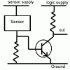
For either of those you could use a circuit like the one attached. You might be able to use one supply for the logic and the Hall sensor supply. The resistor between the base of the transistor and ground needs to be give you a voltage drop of less than 0.5 V with the 2.7 mA, so about 180 Ω. The resistor in series with the collector of the transistor is to pull the logic input up when the transistor is turned off. 1 kΩ would do for most applications.
 

Attachments

  • hall_interface.gif
    hall_interface.gif
    5.6 KB · Views: 173
Last edited:
  • Like
Reactions: kdo
Diver300, you are the greatest! Thanks so much for your quick reply. It appears that the A1150 is definitely a strong candidate for the Hall Effect device used in this application.
I will set up the circuit as you suggest and let you know the results. I'm so jacked!
(Also, thanks to Ian for his quick response - you guys rock)
 
Status
Not open for further replies.

Latest threads

Back
Top