Continue to Site

Welcome to our site!

Electro Tech is an online community (with over 170,000 members) who enjoy talking about and building electronic circuits, projects and gadgets. To participate you need to register. Registration is free. Click here to register now.

  • Welcome to our site! Electro Tech is an online community (with over 170,000 members) who enjoy talking about and building electronic circuits, projects and gadgets. To participate you need to register. Registration is free. Click here to register now.

half-wave from a full-wave bridge rectifier?

Status
Not open for further replies.

mustbuilld

New Member
Hi all

My question is similar to the following thread:

https://www.electro-tech-online.com/threads/w005g-bridge-rectifier.22635/

but it is still not working.

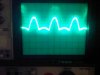
The scope I'm using (Tektronix T922) has a grounded wall outlet and displays a half-wave when connected to a 20 amp 50 volt full-wave bridge rectifier (see images attached).

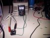
The rectifier is powered by a 0.5K VA variable transformer variac 500VA 0-250V

**broken link removed**

I have not grounded this transformer.

Why doesn't the scope show the full-wave?

cheers.
 

Attachments

  • transformer_bridge_rectifier.jpg
    transformer_bridge_rectifier.jpg
    49.1 KB · Views: 275
  • scope_waveform.jpg
    scope_waveform.jpg
    77.1 KB · Views: 208
You are fliting with danger here. Variac transformers are not isolated transformers. I see that the transformer is a 240VAC input. This leads me to think that you are not in the United States; is this so?

You are likely experiencing the same problem as shown in the image in post #13 of the other thread you referenced. But in your case it is the mains voltage that you are working with because the variac is not an isolated transformer; this is very dangerous.

You need to get a small power transformer to use as the AC source for your rectifier; that will provide the all-important isolation from the grid and you will avoid possible electrocution. Get a transformer with a secondary rated for the highest voltage you want to use, and then you can power its primary from your variac if you want a lower voltage.

If you are in a country with 240 VAC at the standard grid voltage, then one side of your variac is connected to one side of the grid. If the scope is grounded through the wall outlet then the ground clip of your scope is also connected to ground. The output of your rectifier provides a connection to one side of the grid through the variac, because the variac is not isolated (because it's an autotransformer). You could get a serious shock or seriously damage the internals of your scope, depending on where you connect the ground clip of your scope probe.

Please get a small power transformer to continue your experiments.
 
Last edited:
I think that works, now in dual trace mode i see the original half-wave (positive on the scope screen) and missing half wave (negative on the scope screen).

This scope is old i don't see a way to invert ch. 2 which I've connected to the negative terminal on the rectifier, otherwise the entire wave would be displayed positive, is this correct?
That sounds correct.
 
the variac is a foreign model i am living in the united states using 120vac. is this still dangerous?

Yes. Apparently you managed (by a lucky accident) to get the low side of the variac connected to the neutral of the grid, which in the U.S. is connected to the safety ground at the service panel. The ground clip of your scope is connected to the safety ground also. If the plug from your variac were reversed at the wall socket (which it could be if you used one of those 3 prong to 2 prong adapters, for example, or if the outlet is wired incorrectly), you might end up with the hot side of the outlet connected to the low side of the variac. Then when you connect your scope ground clip to the rectifier output you could get a huge flash as you blow up the insides of your scope due to the short across the 120 VAC through the scope ground.

Please get yourself a small power transformer (even Radio Shack has some) and you will be safe.
 
You guys also tried to warn me in the other thread but I think you guys are kinda overstating the danger of working off the mains. I just finished building a 230V power supply a week ago directly off the mains no problem. https://www.electro-tech-online.com/threads/breadboard-voltage-limits.120591/#post994310. Looks a bit different now than whats pictured in the post as I had to swap in some different components to get it working good. Now about to start working on the second stage of the power supply (forward converter).
 
You guys also tried to warn me in the other thread but I think you guys are kinda overstating the danger of working off the mains. I just finished building a 230V power supply a week ago directly off the mains no problem. https://www.electro-tech-online.com/threads/breadboard-voltage-limits.120591/#post994310. Looks a bit different now than whats pictured in the post as I had to swap in some different components to get it working good. Now about to start working on the second stage of the power supply (forward converter).

If you don't understand how dangerous mains can be you've no business playing with it - I never read that thread, but I would certainly say it's an incredibly stupid thing to be doing, I presume others said something similar?.
 
If you don't understand how dangerous mains can be you've no business playing with it - I never read that thread, but I would certainly say it's an incredibly stupid thing to be doing, I presume others said something similar?.

Yes they did. I bought a isolated power supply off ebay but it arrived DOA. After that I said F it and just hooked it up to the mains.
 
OK here in the US AC Mains Power uses a 3 prong outlet. Looking at the two slots the larger slot is Neutral and the small slot is High, the lug is Ground. Neutral and Ground are tied together at the service entry. Between High and either Neutral or Ground you have 120 VAC 60 Hz.

Now looking back at the first image you posted note the symbols used. The line inputs are A and X and the output from the wiper arm is an arrow labeled a and the other output is x. Notice the line between X and x. They are the same point!

I see you have two white wires feeding the transformer A and X inputs. X is Neutral and A is High then things are as they should be. Since X is a straight line to x and X in is low (neutral) then x out is Neutral. However, if A and X are reversed there is a problem. If connected backwards and you use a voltmeter to measure the output it will look just fine. If you place a lamp at the output and increase the voltage up and down the lamp will grow bright and dim. The dangerous part is that the neutral or what should be neutral is now actually a hot 120 VAC with respect to ground.

Your scope should have a 3 wire cord. Line, Neutral and Ground. The outer shell of the BNC scope inputs is actually Neutral or Ground. Therefore if you take the output neutral which is really hot line voltage and connect it to your scope you just shorted 120 VAC hot to ground through the scope chassis. If you place yourself center stage between the two it will be a shocking and memorable experience (assuming you let go).

This is what people have been trying to impress on you. With a pair of white wires and 120 VAC you have a 50/50 chance of getting it correct without an understanding of exactly what is going on.

Ron
 
yeah i didn't know the variac is directly connected to mains on the low side!

now using mains -> power transformer -> variac -> rectifier
 
Yeah, unlike most transformers a variac does not provide mains isolation by design.

Ron
 
yeah i didn't know the variac is directly connected to mains on the low side!

now using mains -> power transformer -> variac -> rectifier

You'll get better results if you set it up like this:

mains -> variac -> power transformer -> rectifier

Especially because the variac you're using is a 240VAC unit. The reason it's better this way is because the wire the variac is wound with is probably smaller than the wire on the secondary of your power transformer and you'll have more copper loss if you draw the current for the rectifier directly from the variac rather than the secondary of the power transformer. A 240VAC variac of a given power capability will have smaller wire than one designed for 120VAC, so more loss when you draw a given current at a low output voltage.
 
It bears mention that just because you have a transformer that isolates you from the power grid does NOT mean there isn't lethal potential. It only eliminates direct to earth ground path errors.

You Might actually be safer with being direct to line through a GFI breaker.
I suspect the best is Both: line -> transformer -> GFI -> {your circuit}.
Transformer isolates any direct to earth, GFI may save you from any mishandling.

This is speculation; I try Really Hard not to work above 48V (~NFPA LV/HV boundary)...
In '91, a GFI breaker saved me from a premature dirt nap. <<<)))
 
Status
Not open for further replies.

New Articles From Microcontroller Tips

Back
Top