Continue to Site

Welcome to our site!

Electro Tech is an online community (with over 170,000 members) who enjoy talking about and building electronic circuits, projects and gadgets. To participate you need to register. Registration is free. Click here to register now.

  • Welcome to our site! Electro Tech is an online community (with over 170,000 members) who enjoy talking about and building electronic circuits, projects and gadgets. To participate you need to register. Registration is free. Click here to register now.

H-Bridge

Status
Not open for further replies.

adrianvon

Member
Hi,

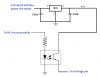
I am going to use two BTS7960 to control an actuator with a maximum current of 25A. Now my questions are:

1) Is it necessary to include external flyback diodes?

2) Is it possible to separate the signal ground from the Power ground? (I want to do this so it will not effect the ground voltage level, hence causing voltage references to be changed.

Thanks in advance.
 
Hi!

1) No, the BTS7960 have internal diodes, those are normally perfectly adapted to the transistor.

2) Yes. There are many ways to do that. you could use chokes, or your could even use an isolated DC/DC converter like the one attached. We use that sometime to totally isolate the logic part from the power part. Of course, only the logic part should be powered by the DC/DC converter, since it can only deliver a few hundreds mA.)

3) I know you didn't ask about that, but, pay a lot of attention to the voltage level. the driver you are using can only take 40V. if the motor (or load) you are controlling is running at 24V, you are allready in big danger, and must prevent the voltage from rising above 24V by all means, otherwise those super transistors modules will blow up before they even get warm! (if the load is inductive, this will happen, trust me)
 

Attachments

  • dcv011515d.pdf
    399.4 KB · Views: 329
Thanks for the reply.

3) I know you didn't ask about that, but, pay a lot of attention to the voltage level. the driver you are using can only take 40V. if the motor (or load) you are controlling is running at 24V, you are allready in big danger, and must prevent the voltage from rising above 24V by all means, otherwise those super transistors modules will blow up before they even get warm! (if the load is inductive, this will happen, trust me)

Why is that please? The actuator works at 12V. Is that safe?

The actuator's motor is a normal DC brushed motor so I assume it is inductive.
 
You mentioned chokes. These are not used to isolate but to reduce noise/distortion right? If so, should I connect the chokes with the ground?

Also, is the circuit attached efficient/practical to use? I used an opto isolator to isolate the PIC and other ICs ground from the power ground. A 7805 is used to reduce the 12V (which will also be powering the motor) to 5V for the H-bridge logic pins. The H-Bridge ground will be connected with the powers ground. This way any references used with the PIC will not be effected by the motor.
 

Attachments

  • Untitled.png
    Untitled.png
    18.6 KB · Views: 203
Thanks for the reply.


Why is that please? The actuator works at 12V. Is that safe?

The actuator's motor is a normal DC brushed motor so I assume it is inductive.

If the supply is 12V, and the transistor can take 40V, then it's okay. The (my) rule of thumb is to consider that the voltage across the transistor can reach 2 x Vsupply, hence 2 x 12V = 24V.
 
You mentioned chokes. These are not used to isolate but to reduce noise/distortion right? If so, should I connect the chokes with the ground?
No the choke need to be connected in series, like this: https://upload.wikimedia.org/wikipedia/en/c/cd/Common-mode-choke.png
Also, is the circuit attached efficient/practical to use? I used an opto isolator to isolate the PIC and other ICs ground from the power ground. A 7805 is used to reduce the 12V (which will also be powering the motor) to 5V for the H-bridge logic pins. The H-Bridge ground will be connected with the powers ground. This way any references used with the PIC will not be effected by the motor.
You still have the same GND for both PIC and the load. noise may still be an issue. if you want to be totally isolated, use the opto couple + isolate both supplies with the component i attached in my previous post. Other wise, both circuits will still share the same GND, and it would be useless to use an opto coupler.
 
Also, the transistor in the mosfet is not wired optimally to be in saturation mode, you may want to read my tutorial below:
**broken link removed**
The load need to be connected to the collector, and the emitter tied to GND, otherwise, the transistor will never saturate :)
 
Thanks for the information. By any chance, do you know of any tutorial about DCV01 or any other DC/DC convertor ? because I never used such IC and I'm not fully understanding how it works.
 
The dcv011515d is really straight forward, just connect the in to the in, and the out to the out!

Adding some filtering capacitor at both ends is important too, but it's all explained in the datasheet, did you take a look at the applications section?
 
Hi again,
i just searched for the dcv011515d on Ebay and it is £32.99 (excluding shipping). Is this IC that expensive? or are there any similar ICs which are cheaper?

Thanks in advance.

Link: **broken link removed**
 
Hi again,

You mentioned the dcv011515D. For my application I have to use the DCV010505 (without D), right? Also, this IC is unregulated. Does this means that the output is unregulated? Can the IC connected with the output(the BTS7960) be damaged in any way?

Thanks in advance.
 
Hi again,

You mentioned the dcv011515D. For my application I have to use the DCV010505 (without D), right? Also, this IC is unregulated. Does this means that the output is unregulated? Can the IC connected with the output(the BTS7960) be damaged in any way?

Thanks in advance.
It means you have to add some filtering caps at the outputs to reduce the voltage ripple.
 
ND in DigiKey part numbers stands for No Discount.

When DigiKey started, they offered discounts on everything in your order based on the total value of the order. I don't remember what the scale was.

But some parts were not applicable to the discount system. Those parts numbers ended in ND.

These days, I don't know of any of their part numbers that don't end in ND, so it really has no meaning anymore.

As for being unregulated, it means that the output voltage will change some under different line and load conditions. There should be info in the data sheet telling you how much the output can change, and under what conditions.
 
Last edited:
Hi,

Thanks for the replies.
If noise or small voltage leak is present at the output of the DC/DC convertor, will it effect the IC internal transformer, thus distorting the input of the DC/DC convertor?
 
Hi,

Thanks for the replies.
If noise or small voltage leak is present at the output of the DC/DC convertor, will it effect the IC internal transformer, thus distorting the input of the DC/DC convertor?


I would say no.. but your question makes me feel that you're using it the wrong way... what do you intend to put at the DC/DC 's output? the logic part right? or the power part of the circuit?
 
The logic part. But since the ground is common for both the motor power and the logic, I was wondering if voltage leak to ground or any noise could cause any distortion at the input DC/DC convertor.
 
Last edited:
Status
Not open for further replies.

Latest threads

New Articles From Microcontroller Tips

Back
Top