Continue to Site

Welcome to our site!

Electro Tech is an online community (with over 170,000 members) who enjoy talking about and building electronic circuits, projects and gadgets. To participate you need to register. Registration is free. Click here to register now.

  • Welcome to our site! Electro Tech is an online community (with over 170,000 members) who enjoy talking about and building electronic circuits, projects and gadgets. To participate you need to register. Registration is free. Click here to register now.

H-Bridge with tip 42 and 120's

Status
Not open for further replies.

Jerran

New Member
Im having some design problems and Im hoping someone can help :) 
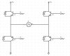
Ive got 2 h-bridges running 2 DC motors at 5V and aprox 1A each, everything works fine if I switch each transistor seperately but if I try to tie bases together to save IO pins my Tip 42's get extremely hot. Ive got teh tip 42's wired on the high side and 120's on the low side. I havent found a way to wire the high and low sides together to make an OR gate effectively yet. Im using 1K resistors on both types of transistors when running the bases independently.

I know my schematic is probably not properly oriented, one of these days Ill write down the proper polarity of the symbols lol.
 

Attachments

  • h_bridge_640.jpg
    h_bridge_640.jpg
    29.5 KB · Views: 1,091
Here is a typical example circuit of a motor-bridge controlled from a micro. One feature of this circuit is that you can't switch both your devices in one leg accidentally creating a short across the supply. No protection diodes are shown.
 

Attachments

  • h_bridge_168.gif
    h_bridge_168.gif
    48.8 KB · Views: 909
The problem with this type of circuit is the top-side 1k resistor. This resistor will slow-down the turn-on of the bottom devices, as well as slowing the turn-off of the top device. Since PNP have a slower mobility than NPN there is a very high chance of a shoot-through - be it a active-region shoot-though.
 
I would also suggest that it's far better to have the transistors switched over, with the collectors together (PNP at top, NPN an bottom). It would require the circuit changing but it's a far better method - there's less voltage drop across the transistors in that mode, and far more available base current to turn them ON.
 
I have added some results with current waveforms to the first post. From this it is clear that there's no noticable current shoot-through problem between top and bottom device.
 
Normall Simulation are pretty good. But in cases like these you are not simulating the circuit correctly. There is not stray inductances. These are critical in power analysis
 
Agree, but his application is for low power. this is a low power drive circuit.
 
Current on its own has nothing to do with power, and it is current that will cause problems with any stray inductance that that cirucit will have.

Output power of a motor is Tw. If the motor is not spinning then there is no power transfer (bar losses). BUT you can still chuck in as much amps as the resistance will allow.

I do desat teasting at work with 1000A, the only power being drawn is to feed the losses. BUT at that amperage even a small amount of stray inductance will cause a problem
 
It is also important to note that in this design (not mine BTW) the two legs each are made up of a push-pull emitter follower (with the top device as a darlington for more current gain), a configuration often used in audio power amplifiers. The disadvantage of this basic circuit with audio use is crossover distortion. This is because of the inherent dead-time between where the bottom device stops conducting and the top one starts as indicated in the graph. This maybe bad for audio but is perfect for switching applications. In audio the biasing arrangement is modified to allow a small idling current through top and bottom device.

The original design was actually put into practice by one of my friends (not his design either) using a HC11 processor with no problems.
 

Attachments

  • p_p_ef_sine.gif
    p_p_ef_sine.gif
    19.3 KB · Views: 767
TheOne said:
The original design was actually put into practice by one of my friends (not his design either) using a HC11 processor with no problems.

It should work OK, but it will lose a fair bit of voltage (more than it needs to!), it's not a very good design choice really.
 
Status
Not open for further replies.

Latest threads

New Articles From Microcontroller Tips

Back
Top