Continue to Site

Welcome to our site!

Electro Tech is an online community (with over 170,000 members) who enjoy talking about and building electronic circuits, projects and gadgets. To participate you need to register. Registration is free. Click here to register now.

  • Welcome to our site! Electro Tech is an online community (with over 170,000 members) who enjoy talking about and building electronic circuits, projects and gadgets. To participate you need to register. Registration is free. Click here to register now.

H-Bridge not working

Status
Not open for further replies.

jacks

New Member
Hi Friends

I am having a hard time getting my comparator controlled H-Bridge to work. It looks like a simple circuit but I have been unsuccessful.

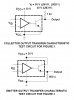
The first comparator seems to be working but when I measure the voltage across the PNP I get 12V and I am not sure why? It is almost like I am getting a short. Also I am not sure what they mean a strobe?

Does anyone have any ideas or should I choose to build a different simple H-Bridge than this one? I have no documentation for this one but schematic as you see it. Thanks

Jacks
 

Attachments

  • HBridge311.GIF
    HBridge311.GIF
    20.3 KB · Views: 242
Which circuit are you using, top or bottom? Say you're using the bottom circuit (and notice that the comparator inputs are swapped at the second LM311, i.e. the non-inverting pin on the first is tied to the inverting pin on the second):

1) Replace the motor with your voltmeter, red lead on the left
2) Apply a low (GND) at the DCC input
3) Your voltmeter should read ca. +12V
4) Apply a high (Vcc) at the DCC input
5) Your voltmeter should read ca. -12V

The strobes are for disabling their respective legs. That is, if you apply a low at the DCC input your voltmeter reads ca. +12V. And then if you make the left strobe low, Mr. voltmeter reads 0V.
 
Saturn1Bygul

Thank you for your reply. I currently have the circuit built as the top one. I did try the bottom one and I was unsuccessful too. Is there a way of calculating voltage around the circuit i.e the top one? I think that way if I know the voltages around then I can troubleshoot better. What do you think? Also what is the difference between the two circuits? Thanks again

Jacks
 
Is there a way of calculating voltage around the circuit i.e the top one? Also what is the difference between the two circuits?

Assert Input A high in the top circuit. If you measure anything but a small voltage (0.5-2V) across Q1 or Q2, they're not conducting.

The bottom circuit is wired so you only have one input to deal with rather than two. High for one direction of rotation, low for the other.
 
Thanks, I will try this first thing tomorrow morning. The circuit has been getting me around circles since last week. I will let you know how it goes.

Jacks
 
I think the LM311 has open collector outputs. A pullup may be needed.
 
I think the LM311 has open collector outputs

Hey Mike,

You got me thinking with your above statement, so I went and looked at the LM311 data sheet. It's got a funky output that can be used an an open collector OR an emitter follower. And the circuit designer is using both outputs simultaneously!? I haven't seen this before, I'm not sure what it would do wired the way it is...

EDIT: After looking at the data sheet further, an example similar to the OPs H-Bridge is given. Four resistors are missing: two 620R units for the upper switches, emitter to base; and another two 620R for the lower switches, base to emitter. Makes sense.
 

Attachments

  • lm311.PNG
    lm311.PNG
    24 KB · Views: 186
  • lm311b.PNG
    lm311b.PNG
    27.6 KB · Views: 235
Last edited:
The data sheet I looked at shows the output as in image below.
 

Attachments

  • 311output.gif
    311output.gif
    11 KB · Views: 156
The data sheet I looked at shows the output as in image below.

Yeah, I know.

Now look at the TI datasheet and see the drawing I appended above. The output stage is wired the same for the Fairchild, NSC, and TI versions, but the TI datasheet points out better how to use it...
 
Well that's wierd. Looks like National does not have the emitter follower pin available. At any rate Jacks circuit is using Pin 7 open collector to drive a transistor.
I guess the original circuit assumes a TI part as National part has pin 1 as ground. Or am I just confused?
 
Well that's weird. Looks like National does not have the emitter follower pin available. Or am I just confused?

They're all identical. They all work in this app. They all have the same output circuit.

In the NSC and Fairchild datasheets pin 1 is labeled "GND" (but notice it's not V-). In the TI datasheet it's labeled "Emit Out." The power amp circuit I appended above is from the NSC datasheet, so they make reference to it too, just not as overtly as the TI. It is weird.

I learned something today...:)
 
Hi Friends

I think it is working now. Thanks Saturn1bguy I think your contribution about putting assert a high on input was the trick. I measured 8V at the collectors and I think that is too much, because the motor was really spinning fast, I just hope I did not break it. I will test it tomorrow again because I tested it once. Thanks to everyone

Jacks
 
the motor was really spinning fast

Make sure your motor voltage and the supply voltage match.

Also, did you add the four resistors mentioned above? (I presume you followed the discussion. The LM311 has a funky output that has both sides (collector and emitter) being used in your circuit, and thus pullups and pulldowns are required for it to work properly. Once you do that, then applying a high to one side or the other should get your motor spinning properly...)
The bridge will switch without the pullups and pulldowns, but it will switch more quickly (less delay) with them. The resistors serve to discharge excess base charge when the circuit turns off. I would never omit them, but there are a lot of people who use similar circuitry, without the pullups and pulldowns, if they are not concerned about speed or high temperatures where leakage might be an issue. Or maybe they just don't know any better.;)
 
Out of curiosity I built an open collector driving a PNP darlington circuit I used a function gen as the driver, and the thing worked. My world no longer makes sense :)

One thing I noted is that the collector driving the darlington seems to oscillate for a bit when the transistor switches off. I also noticed some very large peaks in the oscillation, over the Vcc value. My scope is non digital so I can't show a pic.
 
Last edited:
Oh, I forgot to mention, no pullup on the collector.
 
Hello Again

Saturn1bguy, I did not add the 4 resistors but reduced the voltage and it is still working. I will probably experiment that and see what happens. I will now check the motor voltage to the supply voltage( I am assuming the 5V to the LM311). After this its now implementing the PWM circuit to the bridge to control the speed of the motor. Now that is interesting. Thanks

Jacks
 
Out of curiosity I built an open collector driving a PNP darlington circuit I used a function gen as the driver, and the thing worked. My world no longer makes sense :)
Why did you think it would not work? I'm assuming that your open collector stage was an NPN. When the NPN is off, the PNP (Darlington or not) has no base drive. No base current means (eventually) no collector current.

One thing I noted is that the collector driving the darlington seems to oscillate for a bit when the transistor switches off. I also noticed some very large peaks in the oscillation, over the Vcc value. My scope is non digital so I can't show a pic.
 
Why did you think it would not work? I'm assuming that your open collector stage was an NPN. When the NPN is off, the PNP (Darlington or not) has no base drive. No base current means (eventually) no collector current.

Yes I used an NPN. I just never used a open collector without a pull-up. When the NPN is on, the Darlington base gets a good logic low, when the NPN is off the darlington base sorta floats and momentarily oscillates. I would just add the pullups and pull downs for good measure.
But hey, I can't argue with success...
 
Status
Not open for further replies.

Latest threads

Back
Top