Continue to Site

Welcome to our site!

Electro Tech is an online community (with over 170,000 members) who enjoy talking about and building electronic circuits, projects and gadgets. To participate you need to register. Registration is free. Click here to register now.

  • Welcome to our site! Electro Tech is an online community (with over 170,000 members) who enjoy talking about and building electronic circuits, projects and gadgets. To participate you need to register. Registration is free. Click here to register now.

H-bridge for motor control

Status
Not open for further replies.

konzen

New Member
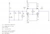
hi, as mentioned in my other post(the one abt virtual ground), i am designing a H-bridge to provide forward and reverse rotation for my DC motor. this is all part of my uni project. can u guys take a look at and comment on my circuit before i actually do the soldering and wiring? any tips and advice would be useful.

in your opinion how big should C1 be?

thx in advance
 

Attachments

  • motordrive.JPG
    motordrive.JPG
    29.8 KB · Views: 247
Hi Konzen,
You don't seem to know anything about Mosfets nor about H-bridges. You should read about how they work.

You had some of the Mosfets upside-down or backwards. You used N-channel where you should have used P-channel.
You turned on the Mosfets through a resistor that isn't needed but nothing was used to turn them off.

Your circuit also needs some logic to sequence the Mosfets so they don't short the supply and smoke and burn.

You are using only a 5V supply so the Mosfets must be Logic-Level type.

I don't think the fan will work with a 1k resistor limiting its current to nearly nothing.
The LED will be very dim also.
 
oh the 5V supplies are to be connected to an altera DE1 board. the switches are just to simulate them in circuitmaker. ok i'll change the mosfets orienatation. but the question im asking is what u think C1 shud be? i'm thinking of using something around 0.5 F. thx for the feedback. will change the resistor values to suitable ones.
 
Why do you need a 0.5F capacitor ? Are you powering it from a regulated supply or fed from a transformer/bridge rectifier ? What is the current and voltage rating for the motor ? What is your input voltage ? Are you using PWM to control the motor speed ? Have you chosen your gate resistors to make sure the gate voltage rises fast enough to prevent excessive heating while the MOSFETs arent in their full on state ?

There are way too many variables to contemplate to be able to criqitue your circuit properly.
 
oh yeah guess i can omit the smoothing capacitor because i'm using a power supply which is regulated. im not sure about the power ratings as the lecturer hasn't given us the motors yet and he isn't sure. will find out more. thanks
 
The resistors are in the wrong places.
The resistors are needed to turn off the Mosfets. Now the resistors do nothing and nothing turns off the Mosfets.

Two of the Mosfets must be P-channel and the other two can be N-channel if you correct their polarity.

What about the 1k resistor in series with the fan. Why is it there?

What about the dim LED? Do you want an LED with only 3mA in it?

Since this is school-work then I won't correct the schematic for you.
 
In short, there are too many things wrong with your circuit for us to solve without doing it for you, which would defeat the whole purpose of you doing it.

What about doing some research on h-bridge, power MOSFETs and LEDs?

Have you asked your lecturer for help?
 
i changed the mosfets to BJTs which i am more familiar with. i just finished building my circuit today and it works fine. now i have to build a simple ADC to convert analog signal to digital to be fed into the microprocessor. thanks alot guys
 
Status
Not open for further replies.

New Articles From Microcontroller Tips

Back
Top