Continue to Site

Welcome to our site!

Electro Tech is an online community (with over 170,000 members) who enjoy talking about and building electronic circuits, projects and gadgets. To participate you need to register. Registration is free. Click here to register now.

  • Welcome to our site! Electro Tech is an online community (with over 170,000 members) who enjoy talking about and building electronic circuits, projects and gadgets. To participate you need to register. Registration is free. Click here to register now.

H bridge design - DIR, PWM, BRAKE

Status
Not open for further replies.
Hi,

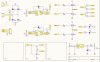
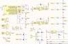
I am designing a powerfull H bridge DC motor controller (>20V, >20A)
My request is that this controller shouly have 3 different inputs:
  • DIR (direction) - 0V for forward, and 5V for reverse
  • PWM - speed control of motor
  • BRAKE - 0V or pulled down for no brake, and 5V for brake turned on
I know how half bridge drivers work, i just need you to help me with implementation of DIR (i think maybe i have solved this), PWM and BRAKE options. I think its not complicated but i cant come up with and idea that would work.

Please help me :)
 

Attachments

  • Schematic - DC motor controller v5.0.JPG
    Schematic - DC motor controller v5.0.JPG
    150.5 KB · Views: 608
I'm interested in your project and I'm too much of a newbie to understand your schematic. I'm curious how you're implementing a brake, is it electrical or electro-mechanical?

Thanks
Kal
 
I'm interested in your project and I'm too much of a newbie to understand your schematic. I'm curious how you're implementing a brake, is it electrical or electro-mechanical?

Thanks
Kal
It is a dynamic braking - like shorting the motor leads together - it gets more difficult to turn the motor when both leads are shorted to ground.
 
It is a dynamic braking - like shorting the motor leads together - it gets more difficult to turn the motor when both leads are shorted to ground.

yep. When the DC motor is coasting, it's acting as a generator with no load. When you load it, (or short the windings) it stops fairly quickly,

Dynamic braking can be taken a bit further and used to charge batteries or even be controlled.
 
Here's https://www.rohm.com/documents/11308/12928/100260.H-BRDG_WP_Jan09.pdf an interesting blurb on the design requirements for a brake/coast system.

It's probably not all of them. One driver I used did have a way of preventing the drivers to be on simultaneously but it wasn't one that implemented brake. In the 1980's there were not very many choices. I kept it simple for hobby motors for a model crane. I used a small H-bridge driver and a relay for dynamic braking for the x/y axis. the gantry used just a relay because of the high current draw. The crane did have dynamic braking, but also had potentiometer settable controlled "limit switches".
The motors had a simple LM317T power supply and a strange sort of overload protection where I made the output goto 1.2 V with an SCR in such a way that the high current starts were ignored.
 
Thanks guys. Very interesting.
This reminds me of dynamic braking of an AC motors where DC voltage is applied to the motor right after the AC is removed. Lots more reading to do :woot:
 
Yep, electric brake for this kind of motor means just shorting motor leads to ground. Thats what i would want to do when i input 5V to BRAKE pin on my board.
Do you guys think it would be a great idea to control mosfet drivers (HI A, HI B, LO A, LO B) with uC (ATTiny84 maybe) and to programm that it has varius inputs (DIR, PWM, BRAKE)?
 
With 20V and 20 A, somehow I don't think you really want to short stuff out that quickly.
You have to keep your circuit safe.
Modulating braking may be beneficial. i.e PWM the brakes. or even just power limit the brakes. I don't know your application.
Slamming on the brakes may have mechanical consequences as well.

Not sure if I saw any current measuring devices, You would have more control, I would think if you measured the legs. Your brake might have two sense resistors.
 
Of course, i could control brakes with PWM also.
How could i measure braking current? And those sense resistorst would have to be really powerfull.
 
Dynamic braking is wasted power, regenerative is (re)using the stored energy.
The general Common definition.
Max.
 
Wikipedia disagrees:

Wikipedia said:
Dynamic braking is the use of the electric traction motors of a vehicle as generators when slowing. It is termed rheostatic if the generated electrical power is dissipated as heat in brake grid resistors, and regenerative if the power is returned to the supply line. Dynamic braking lowers the wear of friction-based braking components, and additionally regeneration reduces energy consumption.

For the purpose of this thread, the OP could:
1. Dissipate the power in the FET's
2. Dissipate the power in a resistor.
3. Dissipate the power in the motor windings
or a combination: particularly 1&3 and 2&3

The OP could modulate braking.

I don't know if batteries would be used. Just mentioned.

Dictionary.com also makes no distinction: https://dictionary.reference.com/browse/dynamic-braking just that the motors become generators.

Max: Your reference to Dynamic Braking please.
 
Hi to all,

I have made some serious changes on my DC motor controller board.
Now i can drive half bridge drivers with ATTiny 44 that has those 3 inputs (PWM, DIR, BRAKE)

Do you see some major mistakes in this schematics or do you think it should work with right program in uC?
 

Attachments

  • 1.JPG
    1.JPG
    183.5 KB · Views: 315
D1 and D7 are backwards (LEDs).

What kind of signal is the PWM input? if a pulsed input signal, you might want to consider changing it to an analog voltage (and removing the two bias resistors). That way, you can read ADC value (assuming it is 10-bit) and transfer that directly to PWM duty cycle (assuming 10 bit). That way, you don't have a processor intensive activity going on to translate the up/down pulses of the input pwm and your processor is freed up to do other things after PWM output is set on a regular basis - depending on pwm frequency and application needs..

Also, I would put a big heat sink on the n-channel mosfets and only switch those. The N-channel usually have lower switching losses than a comparable p-channel.
 
Status
Not open for further replies.

New Articles From Microcontroller Tips

Back
Top