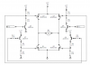
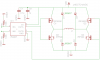
I have two different H-bridge circuits that I would like to show you, attached in the message. More specifically, what are the major differences between H-bridges with intermediate BJT drivers vs. those without? Thanks in advance.
Continue to Site
")