SteveCPerrino
New Member
I designed this circuit based off of a circuit I found online.
Before I buy all the parts, I wanted to ask you guys to see if this would work.
Please tell me if I did something wrong or if something would be a better option. Thanks!
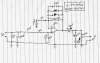
I attached a picture of my schematic
The first two resistors and capacitors form high and low pass filters. The 2nd 1MΩ resistor is there to bias the op amp. The 47pF capacitor and the A100K Pot (Gain knob) form a high pass filter, and the 1KΩ resistor and .01µF capacitor connected to the gain pot form a low pass filter. The A100K Pot and the 1KΩ resistor also set the gain. In the output section, the 10µF electrolytic capacitor makes sure no DC voltage gets into the amp. After the 10µF cap, the A100K Pot and .005µF cap form a variable low pass filter (tone knob). After that comes an A100K Pot (volume knob), which also forms a variable high pass filter with the 10µF cap.
Again, please let me know if there's anything I should change, add, take out, or anything!
Before I buy all the parts, I wanted to ask you guys to see if this would work.
Please tell me if I did something wrong or if something would be a better option. Thanks!
I attached a picture of my schematic
The first two resistors and capacitors form high and low pass filters. The 2nd 1MΩ resistor is there to bias the op amp. The 47pF capacitor and the A100K Pot (Gain knob) form a high pass filter, and the 1KΩ resistor and .01µF capacitor connected to the gain pot form a low pass filter. The A100K Pot and the 1KΩ resistor also set the gain. In the output section, the 10µF electrolytic capacitor makes sure no DC voltage gets into the amp. After the 10µF cap, the A100K Pot and .005µF cap form a variable low pass filter (tone knob). After that comes an A100K Pot (volume knob), which also forms a variable high pass filter with the 10µF cap.
Again, please let me know if there's anything I should change, add, take out, or anything!