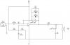
hi , i am new to forum and is studying electrical engineering 2nd year  i m currently working on my project, as the title implies, a guitar fuzz box. i have figure out that D1 , D2 and R4 are the clipper circuits, C2 and C3 stabilizing oscillations, R1 and R2 as a reference voltage via the voltage divider rule, my question is what is C1 for ? and how does R1 and R2 affect the op-amp? i simulate my circuit in circuit maker with a sound signal 0.4v peak to peak, if i m not mistaken, diodes has forward voltage range of 0.6 - 0.7, but the output still produces a Fuzz effect? i think i m wrong with this, i hope you guys can help me with this thanks in advance !
i m currently working on my project, as the title implies, a guitar fuzz box. i have figure out that D1 , D2 and R4 are the clipper circuits, C2 and C3 stabilizing oscillations, R1 and R2 as a reference voltage via the voltage divider rule, my question is what is C1 for ? and how does R1 and R2 affect the op-amp? i simulate my circuit in circuit maker with a sound signal 0.4v peak to peak, if i m not mistaken, diodes has forward voltage range of 0.6 - 0.7, but the output still produces a Fuzz effect? i think i m wrong with this, i hope you guys can help me with this thanks in advance !