Continue to Site

Welcome to our site!

Electro Tech is an online community (with over 170,000 members) who enjoy talking about and building electronic circuits, projects and gadgets. To participate you need to register. Registration is free. Click here to register now.

  • Welcome to our site! Electro Tech is an online community (with over 170,000 members) who enjoy talking about and building electronic circuits, projects and gadgets. To participate you need to register. Registration is free. Click here to register now.

Guitar Distortion/Overdrive Pedal

Status
Not open for further replies.

TrevorP

New Member
Ok heres the dilemna. Ive never made anything electrical in my life but I have been reading heavily about amplification and how to distort sine waves in the past few weeks (I know the basic electrical principles as well.)

Anyway i need to make a distortion/overdrive pedal for guitar for this Thursday coming.

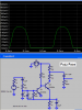
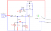
So here is what I have so far:
(The signal gen is the guitar input and the ground on the right is where the output will be.
UPDATE:
---------------------

**broken link removed**


Thanks in Advance,

Trevor
 
Last edited:
Who needs an expensive valve amp when a cheap circuit like this will add all the distortion you need?

Use a potential divider to get the 4.5V.

I thought the potentiometers and volume controls were used to alter the clipping and output voltage.
 
Ok thanks the voltage divider thing worked great...haven't solved any other problems though.... (and Ill probably end up ditching the 2nd channel unless I get that to work.)
 
Can anyone tell me why Im getting clipping like this on the above circuit and not on the bottom of the wave?

**broken link removed**
 
The bottom of the waveform isn't clipped because the top diode in your schematic is broken or is connected backwards.

I simulated the Fuzz Face circuit used by Jimi Hendrix. It is something like yours:
 

Attachments

  • Sim- Fuzz Face.PNG
    Sim- Fuzz Face.PNG
    22.9 KB · Views: 1,180
well I changed the direction of the diodes and it does absolutely nothing.

What I can do though is place a variable resistor with a max resistance of 15k on the V- End of the opamp...and that clips the bottom. then I can adjust the top with the drive resistor.

I dont think that those diodes are even being used.
 
The top diode in your schematic must be replaced because it isn't conducting. Your 'scope shows the bottom diode conducting normally when its signal voltage reaches 600mV.
 
Ok I have 3 questions:

-How would I go about making it so that the top diode conducts as well? Because no matter what Ive tried I just cant get it to clip the bottom also.

-How would I go about reducing my final current?
Because it currently is between +/-200u, and I need it to be between about +/-1.4u.

-What is the input voltage from a guitar?
Because I read somewhere that it was up to 800mV. But I see your test and its around 400mV not cut off.
 
The top diode never conducts because it is always reverse biased. Try connecting the 0V end of R3 to 4.5V.

What do you mean by +/-200u, don't you mean 200:mu:A?

For a start use a single 741 instead of the quad. You could also consider using a lower current opamp like the MC33171, even then you'll need to increase the resistor values by a factor of 10 but you'll be at the mercy of input impedances and bias currents.

Somehow I don't think this is possible, if you're worried about battery life then use a rechargable or mains adaptor.
 
No R3.......
 
TrevorP said:
-How would I go about making it so that the top diode conducts as well? Because no matter what Ive tried I just cant get it to clip the bottom also.
I have fixed your circuit. It was a bad mixture of a single supply and a dual polarity supply.

-How would I go about reducing my final current?
Because it currently is between +/-200u, and I need it to be between about +/-1.4u.
What current? Battery current? The LM348 is very, very old and uses about 10mA of supply current. An old LM324 quad low power opamp uses about 0.8mA of supply current.
What is the resistance of your volume control? If it is less than 10k it uses extra power.

-What is the input voltage from a guitar?
Because I read somewhere that it was up to 800mV. But I see your test and its around 400mV not cut off.
A guitar can make 1V into a 1M load if it is played hard. The opamp has an adjustable gain of 11 up to 200,000.
 

Attachments

  • pedal3.PNG
    pedal3.PNG
    37.3 KB · Views: 940
Thank you very much I'm just going to make those changes now and try it out!

My volume resistance says 10k 40% (I don't know that the 40% is there for its what CircuitMaker put in.)
 
Ok it does sort of round it off but I alas have a few more problems:

**broken link removed**

Here is a graph of the final output...but as you can see it isn't really "clipping":

**broken link removed**

And the final output has been increased (im geussing from the gain) to a higher voltage and I need to bring it back to the same point.

Thanks again.
 
40% is the wiper setting.

Have you tried adjusting R2?
 
Yeah thanks for that 40% thing I had forgot to change it back when I was experimenting with it.

And yes the closer R2 is to zero the more square shaped its going to be it seems.

I know that currently Ill get distortion with the circuit I've got. (albeit very soft I think). But do you know of any way I could get some strong clipping going on? Ive been looking up using a opposite direction diodes in a shunt with the ground but my initial tests have failed. Ill try again though.

(Thanks for all your help Hero999 and Audioguru so far)
 
TrevorP said:
Yeah thanks for that 40% thing I had forgot to change it back when I was experimenting with it.

And yes the closer R2 is to zero the more square shaped its going to be it seems.

I know that currently Ill get distortion with the circuit I've got. (albeit very soft I think). But do you know of any way I could get some strong clipping going on? Ive been looking up using a opposite direction diodes in a shunt with the ground but my initial tests have failed. Ill try again though.

You've got FAR too little gain, increase the feedback resistor to 220K or 470K, get some clipping going on!.
 
The diodes in the feedback loop of an opamp creates "soft clipping". If you want nasty, acid-rock "hard clipping" then try it this way:
 

Attachments

  • pedal4 hard clipping.PNG
    pedal4 hard clipping.PNG
    41.4 KB · Views: 536
yes that thing Audioguru...wow it worked this time...weird.

As for the comment about raising the feedback resistor really high Im still only getting an output voltage of like 4.479.
 
Ok here is my one last problem...I think..

Input Current:
**broken link removed**

Output Current:
**broken link removed**

Now I'm only going to assume that they have to be the same.

How could I lower the current values without the voltage as well? I'm thinking its just as easy as a parallel circuit. But I could be wrong.
 
Status
Not open for further replies.

Latest threads

New Articles From Microcontroller Tips

Back
Top