Electro Tech is an online community (with over 170,000 members) who enjoy talking about and building electronic circuits, projects and gadgets. To participate you need to register. Registration is free. Click here to register now.
Welcome to our site! Electro Tech is an online community (with over 170,000 members) who enjoy talking about and building electronic circuits, projects and gadgets. To participate you need to register. Registration is free. Click here to register now.
haha, I love growing things and have been trying to spice up my dorm room with herbs and some veggies. The sad thing is, almost all the information on LED grow lights either come from some place trying to sell you an overpriced kit, or mary jaine growers. I even saw a how-to on converting a spare dresser into a hidden marijuana grower (using CFL's).
I've been trying to grow mint and radishes, and my current setup isn't powerful enough.
probably if you have can hack a digital alarm clock which goes off at those specific times, wire the speaker output to feed to a latch which turns on a light driver?
But then you would need to know programming in assembly or C and also some basic soldering skills. There are numerous PIC based clock projects in the internet from which you could ideas.
From in the info. you posted, I think you need a PIC connected to a watch crystal (or a dedicated RTC chip if ), and a relay to control the light.
I'd rather not use a microcontroller, it seems like overkill. I do know how to program however (I'm primarily a programmer, hardware is only a hobby).
I think I'm gonna go with the first suggestion, it makes a lot of sense, but if I wanted to do dimming to match fading sunlight I'd probably have to use a microcontroller.
A PIC would be easiest. But building an electronic solution sould be easy. Just use one of the counter IC's such as the 4060. Set the input oscillator to a frequency that gives the maximum count in a 24-hour period. Do a D/A conversion of the low order bits to get the fade in/fade out effect, or else convert those bits directly to a PWM signal. It's just a logical puzzle, but a smart college guy can figure it out
MJ growers are the best indoor growers in the world. I would just find some forums and learn what they do.
Don't worry about fading the light. Don't use LEDs as they do not have broad spectrum light, and are way more expensive than florescents. Unless you are going to let the plants go to seed, just leave the light on all the time. They do not need the darkness when doing solely veg growth, only when flowing/seeding.
Yeah, I knew this guy wasn't an MJ grower when he talked about wanting to turn the lights off. I think the MJ growers leave them on 24/7.
Power compact florescent bulbs are a good technology. I used them over my 55 gallon planted aquarium and they were plenty. I would just get a commercial power compact fixture and use the light timers available at the local hardware store.
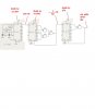
you have to use a high frequency crystal oscilator and a divider if you want to get good accuracy. i remmeber i have posted a diagram long before for some timer for LED control, that gives 1 sec pulse, this can be fed to a divider to get 8 hr, then after 8 hr count it can set the reset of counter via another counter that will enable the reset after 16hr (8hrx2) count. then it will reset after 8hr. if you need complete circuit i can post shortly.
see the attached time base, hope it will give a single pule after every 8hrs, if any one can simulate it? also hee needs 8 hr then 16 hr signals, so the out put can be fed to a 4017 and to some logics to work as required.
Edit: .made a mistake connect U1A to pins 13 & 6 of last IC, resets can be done using the free pin(now connected together) of AND gate inputs for last two steps and the 1st ICs direct input.
This site uses cookies to help personalise content, tailor your experience and to keep you logged in if you register.
By continuing to use this site, you are consenting to our use of cookies.