Continue to Site

Welcome to our site!

Electro Tech is an online community (with over 170,000 members) who enjoy talking about and building electronic circuits, projects and gadgets. To participate you need to register. Registration is free. Click here to register now.

  • Welcome to our site! Electro Tech is an online community (with over 170,000 members) who enjoy talking about and building electronic circuits, projects and gadgets. To participate you need to register. Registration is free. Click here to register now.

Glowing LEDs and 12v motor

Status
Not open for further replies.

blckscab

New Member
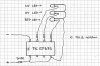
Im making a wood sculpture which is powered by the mains (uk, which i think is 240v) and requires a motor to move a part of it, and i want a few red LEDs to 'glow' (as in brighter -> dimmer -> brighter etc and so forth) around it lighting up the rotating piece.

The only problem is that i have no knowledge on electronics at all and wondered into a area i am not familiar with. So i have come seeking for your guidance :p...

I have found a few components that i figured could be of use and saved...

A few plug adapters that convert mains into 12V (AC and DC), switches and a AC 12v 50/60HZ 1/1.5w motor.

Obviously i can buy more components

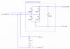
But can anyone help a or produce a simple schematic showing how i can wire all these up without blowing myself up or burn my home down, lol.
If it makes it easier, i dont have to go for the glowing affect. Since im guessing that would be going into complicated stuff. Would be good to have though.

Any help would be great! Thank you :eek::)
 
Last edited:
Go for a 12VAC adaptor and make sure it provides enough power for your motor.

The LEDs will require DC so you need a filer capacitor and a bridge rectifier. For the fading effect, I recommend the circuit linked below.
 
I clicked on the Video and heard an American advertisment. The guy spoke some syllables so fast that it sounded like he is hyper or on drugs.
 
I dont think the video is what hero is trying to bring to our attention ;) That is just a ad.

So i can use a LM1458 IC to make the glowing effect of the LEDs.
But can the chip be bought to do that already or will i have to programm it in any way?

Also, how would i attach this circuit to a 12v power source and the motor?

thanks :)


Hi,
Have a look thru this pdf.

EDIT: and this link: https://www.rainbowcandles.co.uk/
 

Attachments

  • RAINBOWLED[2].pdf
    227.9 KB · Views: 450
Last edited:
I dont think the video is what hero is trying to bring to our attention ;) That is just a ad.

So i can use a LM1458 IC to make the glowing effect of the LEDs.
But can the chip be bought to do that already or will i have to programm it in any way?

Also, how would i attach this circuit to a 12v power source and the motor?

thanks :)

Hi blckscab,

Man, that nickname sounds like something which would need a lot of antibiotics. ;) Anyway, yeah, that LM1458 required no programming or anything. It's a type of IC called an "op amp", if you'd like to Google the term for more infomation. (Actually, it's a dual op amp, in that the IC contains 2 op amps). Just hook it up as indicated on the schematic.

Also, "glowing" means "emitting light". The term you're looking for is "fading", as in "the LEDs faded slowly from dark to bright and back again".

How heavy is the part of the sculpture which needs to be moved by the motor? Does the motor have the power to move it OK? Also, does the moving part just need to go around and around or does it have to go back and forth (oscillate)?


Torben
 
That's a point, 1W is a pretty small motor and won't be able to lift heavy things very fast.
 
Last edited:
Lol, its a terrable name really... But since i have everything registered to it already so i cant easily change it :p hehe

I did wonder why the IC was split on the schematic, but that has helpped me understand that :)

'fading' does make more sence, thanks for the correction :eek:

i have tested the motor with the sculpture a few times and it seems to handle it ok. the pieces moved are hanged on arbours and part of a gear train so it doesnt actually take much force to make them move round :)

See, i can figure out all of the making and mechanics of it. Its just the electronics! Lol.:p
 
Hey, could i use this circuit shown in this simple picture?

I think it will have to be programmed beforehand, but i can get the software here -> **broken link removed**
and i can always buy a PIC programmer off of ebay or somewhere?

:confused::p
 

Attachments

  • pic12F675.JPG
    pic12F675.JPG
    41.2 KB · Views: 206
I'd think that unless you already had the programmer and a little experience with PICs, the schematic that Hero posted a link to would be a good place to start for the fading LEDs. You could then run the motor and the fading LEDs from the same 12V source. I know that the schematic Hero linked to specifies 9V in but it should run just fine off 12V (though you might want to tweak a couple of the resistor values to get the fade rate to what you want, and to control the current to the LEDs).

You didn't say whether the motor just needs to continuously run in one direction or whether you need to reverse it.


Torben
 
It needs to just go in one direction.

Where should i put the motor in the circuit without it affecting the rest of the circuit? Would it work fine if i just connected one end to +12v and the other to 0v before the rest of the circuit?:eek:
 
It needs to just go in one direction.

Where should i put the motor in the circuit without it affecting the rest of the circuit? Would it work fine if i just connected one end to +12v and the other to 0v before the rest of the circuit?:eek:

Assuming that the current drawn by the motor isn't so much that it causes the 12V to sag below what the fading circuit requires, then yes, it should be fine.

What is the current rating of your 12V power source?

Oops. Sorry, I just noticed that the motor wants 12VAC, not 12VDC. My mistake. So you'd need:

o A 240VAC to 12VAC adaptor to run the motor.
o Either of:
a) a rectifier bridge going through a filter capacitor (as Hero stated), possibly into a voltage regulator (if you like, it's not really necessary here) to provide the DC source to run the fading circuit from; or
b) another adaptor (240VAC to 9, 12, or so VDC) to separately power the fading circuit.

I imagine that you'd prefer just to run one adaptor to the sculpture, though, so I'd recommend option a).

I'll see if I can cobble together a simple schematic in a while.


Torben
 
Last edited:
ah, that would be really useful :D
I can get a 12v DC motor if it makes things easier... Infact i think i have one buried in my spare parts draw somewhere...
Id rather it was simple so i can understand it, and then re-use that circuit in any future projects.
 
Hi again,

OK, this is a simple unregulated rectification and filtering circuit for the sculpture:

rect_filter_1-png.21019


I'd suggest trying an adaptor with 12VAC output on this, but maybe try a 9VAC or so if you have it, since after rectification and filtering, the 12VAC in will result in more than 12VAC out. If the motor causes the adaptor to sag sufficiently, though, a 12VAC adaptor may be necessary.

R1 and C1 are there to protect the rest of the circuit from inductive kickback from the motor when the thing is turned off. Your motor isn't very big so that might not be much of an issue, but I'd include them just to be safe. Use a 1/2W or 1W resistor for R1 and a non-polarized (important!) capacitor for C1. (Note that I'm no expert on RC snubber design but I believe the values given should be OK here.)

The four 1N4001 diodes rectify the 12VAC to DC, which comes out as a DC half-sine wave at 100Hz. C3 smooths that to something resembling a steady DC voltage, after which you can use the output to power the fading circuit. If you find that the fading circuit behaves oddly you can add another 4700uF cap alongside C3 to smooth the output even more, but at 100Hz you shouldn't notice anything anyway.


Hope this makes some sense and helps a bit,

Torben

P.S. I also hope any glaring goofs are corrected by those who know better, as always. I haven't built this, just drawn it out. :)
 

Attachments

  • rect_filter_1.png
    rect_filter_1.png
    6.7 KB · Views: 442
Last edited:
Thats great! As long as i have a Schem. with the right values and components, ill be fine working from that to make a circuit :D

Im not so sure about that non polarised capasitor though...
The closest i could find to it was this...

**broken link removed**
:confused:
 
Torben suggested a .1 uf capacitor, not a 1 uf.
Something like so.
http://search.digikey.com/scripts/DkSearch/dksus.dll?Detail?name=478-2430-2-ND


Or if Ebay is your choice.
**broken link removed**

Yeah, I did, but only because that's a value I saw used in a similar application. I'm still chewing through a PDF on snubber design--but right now I'm working on fixing Grandma's pressure washer, so the snubber might have to wait until tonight. ;)

Here's the link to the RC snubber design doc I'm reading through: https://www.electro-tech-online.com/custompdfs/2008/07/PULSE-APPGUIDE.pdf
in case anyone is interested.


Torben
 
Doh!
Just figured out the capacitor values... 4700nF isnt the same as a 4700µF....Went and bought the wrong ones, lol.
I understand it now but the larger value capacitors all seem to be electrolytic and have a required voltage. What voltage capacitors do i need or do i just need to get ones under 12v?

gettin there slowly :p hehe
Thanks for the help guys :eek: would never of got this far with the circuit without your help:D
 
Doh!
Just figured out the capacitor values... 4700nF isnt the same as a 4700µF....Went and bought the wrong ones, lol.
I understand it now but the larger value capacitors all seem to be electrolytic and have a required voltage. What voltage capacitors do i need or do i just need to get ones under 12v?

For a circuit designed for 12V operation, your lowest available (that I know of) option is 16V, and that's pushing it. I'd go for at least a 25V-rated part to make sure you've got the headroom to not exceed the cap's rating even in a worst-case scenario. The 4700uF cap will be a polarized electrolytic, so make darn sure you hook its negative lead to ground and not the other way around--otherwise it could pop and get hot stinky goop all over the place.

The 0.1uF cap on the RC snubber across the motor leads, on the other hand, doesn't care which way it is hooked up, since it *must* be non-polarized: it's operating on AC, so its positive and negative side will be swapped at 50Hz.


Torben
 
Status
Not open for further replies.

Latest threads

New Articles From Microcontroller Tips

Back
Top