Continue to Site

Welcome to our site!

Electro Tech is an online community (with over 170,000 members) who enjoy talking about and building electronic circuits, projects and gadgets. To participate you need to register. Registration is free. Click here to register now.

  • Welcome to our site! Electro Tech is an online community (with over 170,000 members) who enjoy talking about and building electronic circuits, projects and gadgets. To participate you need to register. Registration is free. Click here to register now.

Getting this VHF band II VCO to work

Status
Not open for further replies.

alexander3133

New Member
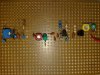
I constructed this VHF back II VCO to work with FM. I simulated this circuit in MultiSIM with initial condition set to zero and it works. Once I implemented into hardware, it does not work and refuse to give any oscillation, any idea what went wrong with this design?

Both C9 and C5 are trimmer capacitor.
 

Attachments

  • vco_prob..png
    vco_prob..png
    33 KB · Views: 268
Last edited:
You've go no power supply decoupling caps. The bias circuit for Q2 is really poorly designed and beta/temperature dependent. 2n3904's don't have much gain above 100Mhz, but will marginally work in those circuits.
 
Last edited:
Could you further explain the statement?
You need some capacitors (10uF, 0.1uF & 1000pF) across each battery, but physically located as close as possible to the oscillator and amplifier. (You can get away without the 10uF for now, but it helps bypass noise at audio frequencies.)
Did you build the circuit on a PCB and keep the wiring short? It won't work properly on a breadboard.
 
Last edited:
You need some capacitors (10uF, 0.1uF & 1000pF) across each battery, but physically located as close as possible to the oscillator and amplifier. (You can get away without the 10uF for now, but it helps bypass noise at audio frequencies.)
Did you build the circuit on a PCB and keep the wiring short? It won't work properly on a breadboard.

I built this circuit on a stripboard and I already cut the extra legs for the components to make the wiring short. Images attached are front and back of the circuit. Although I know my soldering skill not really good, but I doubt it still acceptable. The varicap is soldered on the back of the stripboard as it is a surface mount component.
 

Attachments

  • 04032010137..jpg
    04032010137..jpg
    1.4 MB · Views: 162
  • 04032010136..jpg
    04032010136..jpg
    784.8 KB · Views: 216
Instead of low Q chokes in your tuned circuits, you should be using high Q air wound inductors. Mount the inductors that are closest to each other so they are rotated 90 degrees from one another. This will minimize inductive coupling. Though it is hard to tell from the pictures, make sure that any PCB tracks are cut off short and are not acting as long antennas. ie: Don't let the PCB traces be any longer than needed.
 
Status
Not open for further replies.

Latest threads

Back
Top